LNG power plant and operation method thereof
- Summary
- Abstract
- Description
- Claims
- Application Information
AI Technical Summary
Benefits of technology
Problems solved by technology
Method used
Image

Examples
first embodiment
[0035] [First Embodiment]
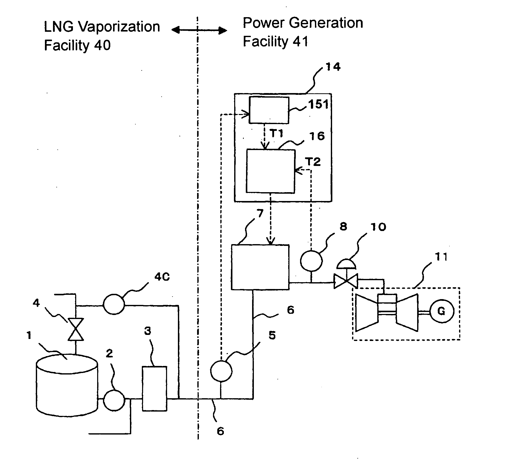
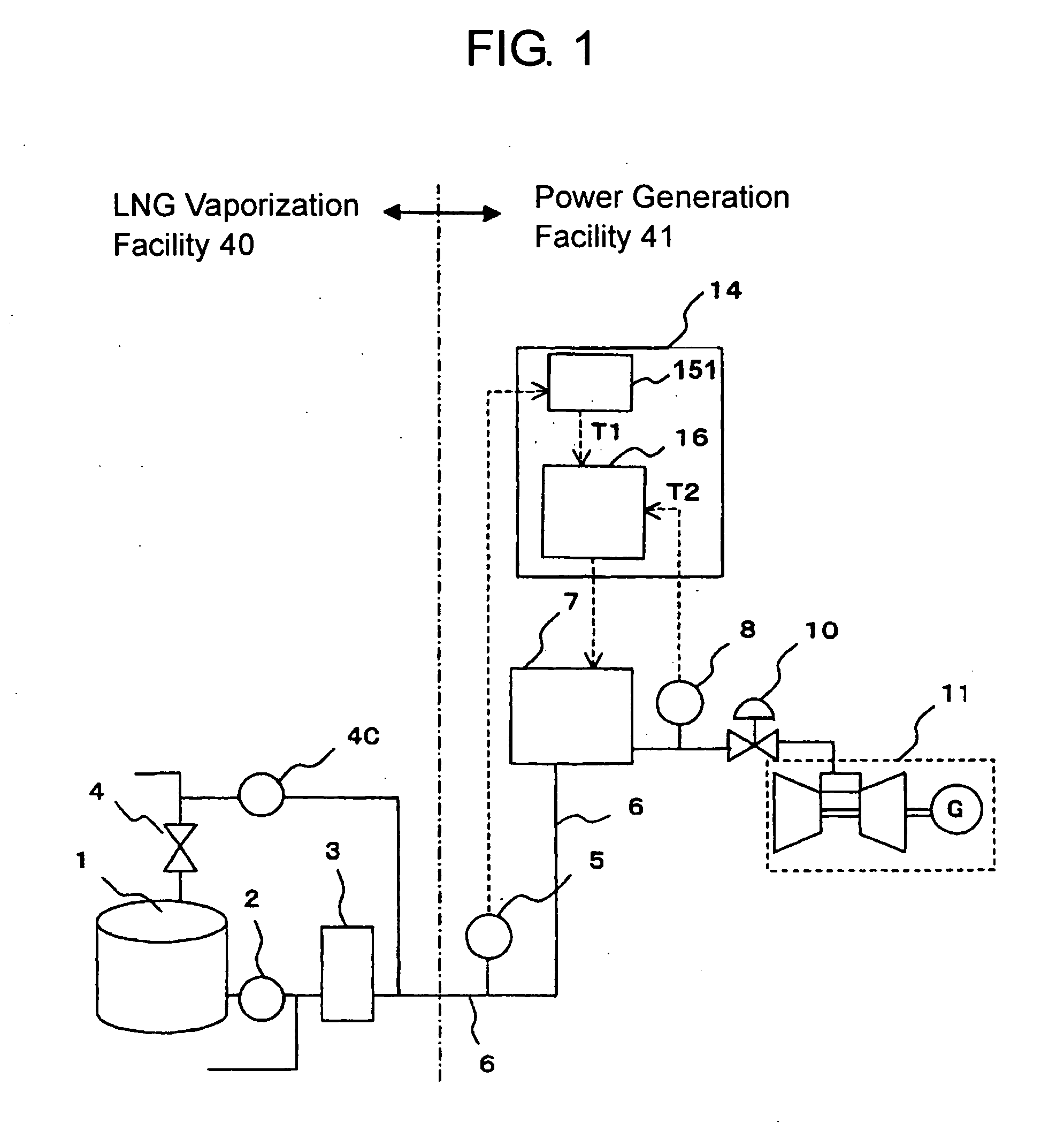
[0036]FIG. 1 is a block diagram of an LNG power plant according to the first embodiment of the present invention. The LNG power plant has an LNG vaporization facility 40 and a power generation facility 41.
[0037] The LNG vaporization facility 41 has a plurality of LNG storage tanks 1. The LNG storage tanks are thermally insulated. LNG storage tanks 1 are connected to a common BOG compressor 4C through respective BOG outlet valves 4. The LNG storage tanks 1 are also connected to a common vaporizer 3 through respective boost pumps 2. From the BOG compressor 4C and the vaporizer 3, a gas feed pipe 6 extends to the power generation facility 41.
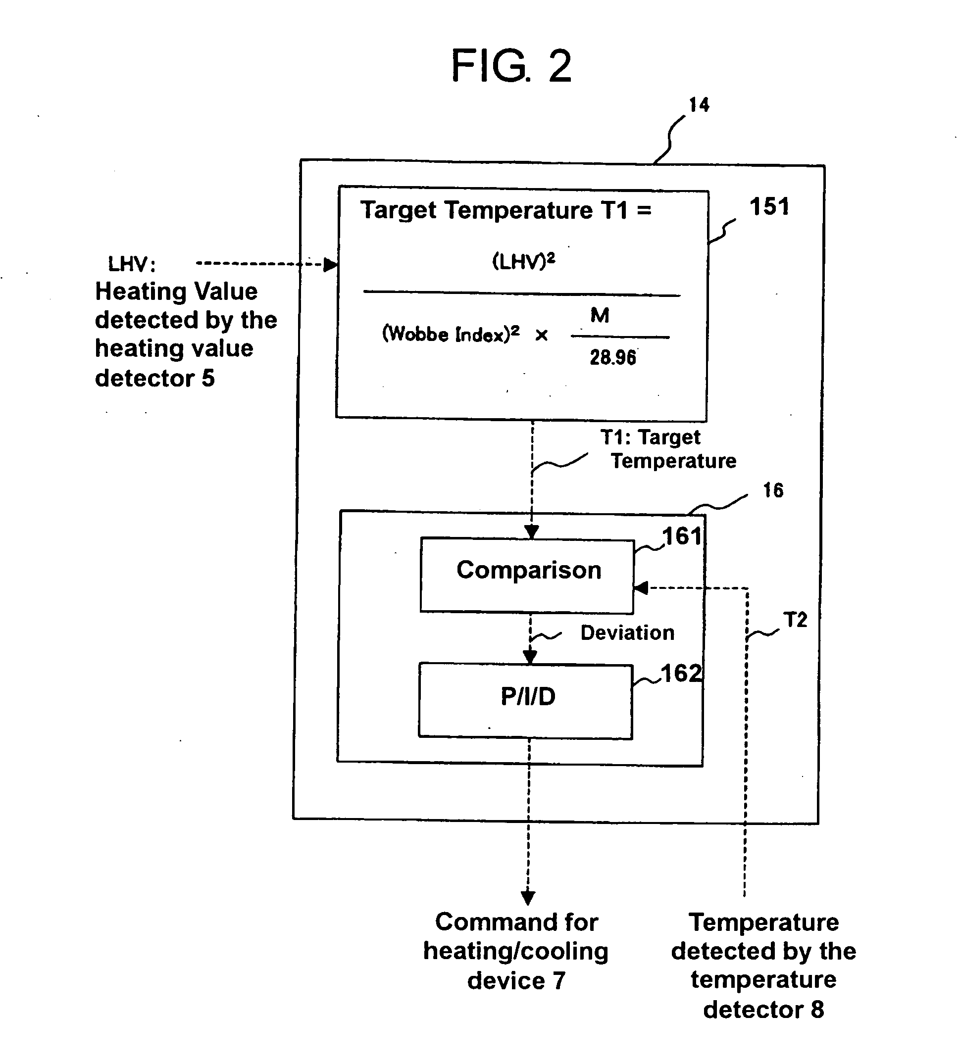
[0038] In the power generation facility 41, the gas feed pipe 6 extends through a fuel adjust valve 10 to the gas turbine power generation unit 11. A heating value detector 5, such as a calorimeter or gas chromatography for detecting or calculating a gas heat generation quantity, is attached between the LNG vaporization f...
second embodiment
[0050] [Second Embodiment]
[0051]FIG. 3 is a block diagram of a LNG power plant according to the second embodiment of the present invention. As shown in FIG. 3, the present embodiment is partly different from the first embodiment in that the temperature control device 14 receives a signal from the BOG outlet valves 4 instead of the heating value detector 5.
[0052] A target temperature calculator 152 installed in the temperature control device 14 receives a signal indicating the number of open BOG outlet valves 4. This signal is used as a state quantity signal equivalent to the heating value in place of the heating value detected by the heating value detector 5. A signal of the number of the open BOG valves 4 is inputted to the target temperature calculator 152.
[0053] The other features of the structure are not different from those of the first embodiment shown in FIGS. 1, 2 and 7. The identical reference symbols are assigned and detailed descriptions thereof is omitted here.
[0054] ...
third embodiment
[0057] [Third Embodiment]
[0058]FIG. 4 is a block diagram of the LNG power plant according to the third embodiment of the present invention. FIG. 5 is a block diagram of a temperature control device used in the present embodiment.
[0059] If the number of the operated BOG outlet valves 4 is changed in the LNG vaporization facility 40, a change of the heating value of the fuel gas has a small delay from the change of the number of the operated BOG outlet valves.
[0060] Therefore, if a detection signal from the heating value detector 5 such as a gas calorimeter or a gas chromatography is introduced to the temperature control device 14, as in the first embodiment, the response speed can be lower but the accuracy can be higher, compared with the case in which a signal indicating the number of the operating BOG outlet valves 4 is introduced to the temperature control device 14, as in the second embodiment.
[0061] Inversely, if the operating BOG outlet valve number signal is introduced to t...
PUM
 Abstract
Description
Claims
Application Information
 - R&D Engineer
- R&D Manager
- IP Professional
- Industry Leading Data Capabilities
- Powerful AI technology
- Patent DNA Extraction
Browse by: Latest US Patents, China's latest patents, Technical Efficacy Thesaurus, Application Domain, Technology Topic.
© 2024 PatSnap. All rights reserved.Legal|Privacy policy|Modern Slavery Act Transparency Statement|Sitemap