Rotation transmission device

a transmission device and rotating technology, applied in the direction of mechanical actuated clutches, interlocking clutches, couplings, etc., can solve the problems of reducing the torque transmitted from the outer ring to the armature, difficult to not enough interference left for the rotor to remain secure, etc., to achieve reliably engage the two-way clutch, minimize the leakage of magnetic field, and reduce the effect of magnetic field leakag

Active Publication Date: 2006-08-24
NTN CORP
View PDF59 Cites 9 Cited by
  • Summary
  • Abstract
  • Description
  • Claims
  • Application Information

AI Technical Summary

Benefits of technology

[0014] With this arrangement, it is possible to minimize leakage of the magnetic field produced when the electromagnetic coil of the electromagnet is energized to the outer ring through the rotor guide. Thus, by energizing the electromagnetic coil, the armature can be reliably attracted to the rotor, so that it is possible to reliably engage the two-way clutch.
[0015] Also, by pressing the rotor into the rotor guide, the interference therebetween will remain constant when they are heated and expanded because they are made of magnetic materials having the same or substantially the same coefficients of linear expansion. Thus, the rotor and the rotor guide can be reliably coupled together without the need for means for preventing rotation and axial movement rela...

Problems solved by technology

This in turn reduces the torque transmitted from the outer ring to the armature, thereby making it difficult to reliably engage the two-way clutch.
Thus if the rotor is pressed into the rotor guide, when the rotor and the rotor guide are heated and expanded, there will not be enough interference left for the rotor to remain secured to t...

Method used


Image

  • Rotation transmission device
  • Rotation transmission device
  • Rotation transmission device

Examples


Embodiment Construction

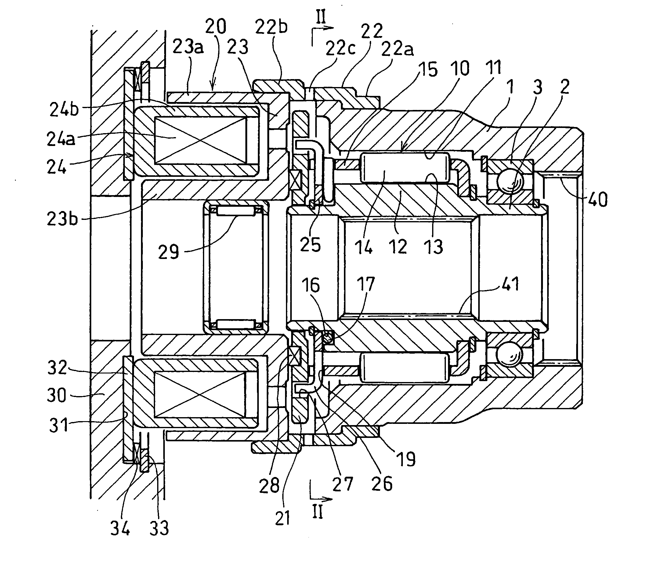
[0024] Now, the embodiment of the present invention is described in detail with reference to the accompanying drawings. As shown, the rotation transmission device of the embodiment includes an outer ring 1 and an inner ring 2 mounted inside the outer ring 1. The outer ring 1 and the inner ring 2 are rotatably supported on each other through a bearing 3.

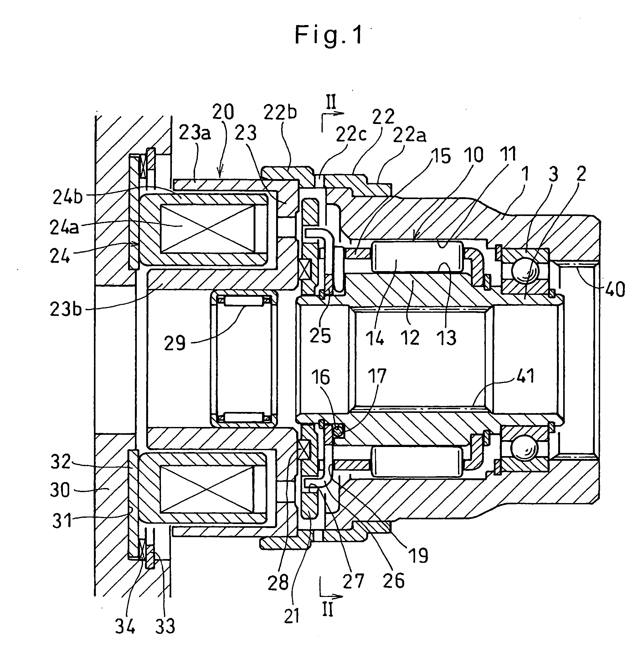
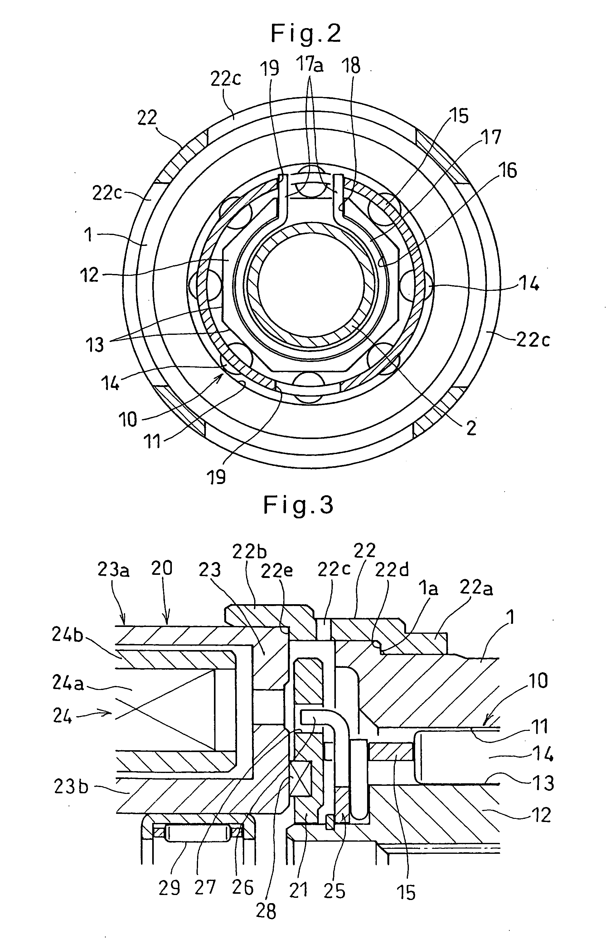
[0025] Between the outer ring 1 and the inner ring 2, a roller type two-way clutch 10 is mounted which comprises a cylindrical surface 11 formed on the inner periphery of the outer ring 1, a plurality of cam surfaces 13 formed on the outer periphery of a large diameter portion 12 of the inner ring 2 so as to face the cylindrical surface 11, rollers 14 each mounted in one of wedge-shaped spaces defined between the cylindrical surface 11 and the cam surfaces 13 and narrowing toward the circumferential ends thereof, and a retainer 15 holding the rollers 14.

[0026] As shown in FIG. 2, a C-shaped switch spring 17 is received in a recess 1...


PUM


Abstract

A rotation transmission device includes inner and outer rings, a two-way clutch mounted between the outer and inner rings, and an electromagnetic clutch mounted adjacent to the two-way clutch. The electromagnetic clutch includes a rotor guide pressed onto the outer ring at its open end and a rotor pressed into the rotor guide. The rotor guide is made of a magnetic material having the same or substantially the same coefficient of linear expansion as the material of the rotor. Thus, even when the rotor guide and the rotor are heated and expanded, the interference between the rotor and the rotor guide remains substantially constant. Therefore, the rotor and the rotor guide can be reliably coupled together with a simple structure and at a low cost.

Description

BACKGROUND OF THE INVENTION [0001] The present invention relates to a rotation transmission device for selectively transmitting power from input to output members of a drive train. [0002] JP patent publication 2003-120719A discloses a rotation transmission device for selectively transmitting driving torque to the front, auxiliary drive wheels of a four-wheel drive vehicle of the front-engine, rear-drive layout. [0003] This conventional rotation transmission device includes an outer ring coupled to a propeller shaft, an inner ring coupled to a pinion shaft of a differential, and a two-way clutch mounted between the outer and inner rings. An electromagnetic clutch is provided adjacent to the two-way clutch to selectively engage and disengage the two-way clutch. When the two-way clutch engages, the outer ring and the inner ring are coupled together, so that the rotation of the outer ring is transmitted to the inner ring. [0004] The two-way clutch includes a cylindrical surface formed o...

Claims


Application Information

Patent Timeline
IPC IPC(8): F16D27/10F16D15/00
CPCF16D27/10F16D27/14F16D41/088
Inventor YASUI, MAKOTOSATO, KOJI
Owner NTN CORP
Why Eureka
Try Eureka