Probe for a scanning magnetic force microscope, method for producing the same, and method for forming ferromagnetic alloy film on carbon nanotubes
a scanning magnetic force microscope and microscope technology, applied in the direction of instruments, material analysis using wave/particle radiation, nuclear engineering, etc., can solve the problems of difficult to use carbon nanotubes as scanning magnetic force microscope probes, insufficient measurement of samples with irregular surfaces, and general coating of conventional probes, etc., to improve the directivity of magnetic field, improve the resolution, and suppress the leakage of magnetic field
- Summary
- Abstract
- Description
- Claims
- Application Information
AI Technical Summary
Benefits of technology
Problems solved by technology
Method used
Image
Examples
example 1
[0059]A multi-walled carbon nanotube with a diameter of about 10 nm was attached onto a base, and this sample was placed into a sputtering device in which Fe—Co (Fe: 20 at % and Co: 80 at %) sputtering target had been mounted. After Ar gas was introduced at 10 sccm and the gaseous pressure was adjusted to 0.3 Pa, 100 W of radio frequency electric power (RF) was applied to generate plasma. Under this condition (hereinafter referred to as “film formation condition A”), the film-forming treatment was carried out for 4 min and 15 sec.
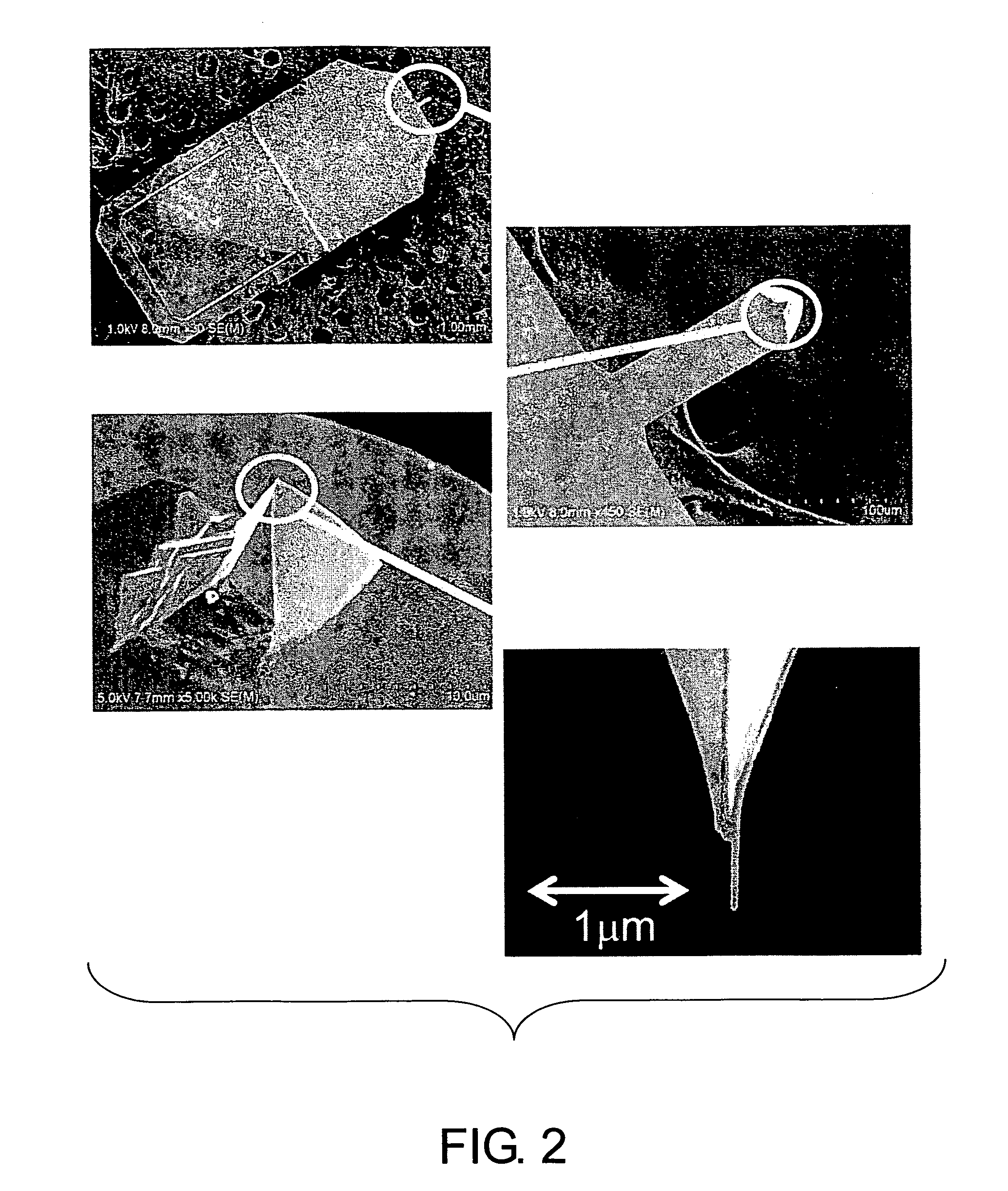
[0060]The results demonstrated that the Fe—Co ferromagnetic alloy film of the sample had a thickness of 10 nm, as determined from its electron microscopic images. Thus, the mean growth rate of ferromagnetic alloy film was found to be 2.35 nm / min under this condition. The surface roughness of the sample prepared as above was determined at flat portions of the base tip using atomic force microscope. The obtained roughness profile is shown in FIG. 4. The arith...
example 2
[0063]A sample base was prepared through a similar film-forming treatment as described in Example 1, with the exception that the pressure was changed from 0.3 Pa to 1 Pa (hereinafter referred to as “film formation condition B”).
[0064]As a result, the growth rate decreased to 1.48 nm / min, and the surface roughness Ra(L=10 μm) of the formed ferromagnetic film was improved to 0.9996 nm (for comparison, Ra(L=1 μm) was 0.1739 nm). As with the case of Example 1, clear micrographic images could be also obtained for the 1200-kFCI magnetic storage medium.
example 3
[0065]A sample base was prepared through a similar film-forming treatment as described in Example 1, with the exception that the input radio frequency electric power was reduced from 100 W to 50 W (hereinafter referred to as “film formation condition E”).
[0066]As a result, the growth rate decreased to 1.23 nm / min, and the surface roughness Ra(L=10 μm) of the formed ferromagnetic film was improved to 1.046 nm (for comparison, Ra(L=1 μm) was 0.2636 nm). As with the case of Example 1, clear micrographic images could be also obtained for the 1200-kFCI magnetic storage medium.
PUM
| Property | Measurement | Unit |
|---|---|---|
| Ra | aaaaa | aaaaa |
| thickness | aaaaa | aaaaa |
| thickness | aaaaa | aaaaa |
Abstract
Description
Claims
Application Information
 - R&D
- Intellectual Property
- Life Sciences
- Materials
- Tech Scout
- Unparalleled Data Quality
- Higher Quality Content
- 60% Fewer Hallucinations
Browse by: Latest US Patents, China's latest patents, Technical Efficacy Thesaurus, Application Domain, Technology Topic, Popular Technical Reports.
© 2025 PatSnap. All rights reserved.Legal|Privacy policy|Modern Slavery Act Transparency Statement|Sitemap|About US| Contact US: help@patsnap.com


