
Open-phase detecting method and apparatus

a detection method and open-phase technology, applied in the direction of electric variable regulation, process and machine control, instruments, etc., can solve the problems of hard structure, 180° phase difference, and output of logic signals rb>2/b> or sb>2/b> corresponding to open-phase,

Inactive Publication Date: 2006-08-24
YASKAWA DENKI KK
View PDF8 Cites 26 Cited by
  • Summary
  • Abstract
  • Description
  • Claims
  • Application Information

AI Technical Summary

Benefits of technology

[0014] The preferred embodiments of the present invention have been developed in view of the above-mentioned and / or other problems in the related art. The preferred embodiments of the present invention can significantly improve upon existing methods and / or apparatuses.
[0015] Among other potential advantages, some embodiments can provide an open-phase detecting method capable of achieving a reduced cost by employing a simple hardware structure.
[0016] Among other potential advantages, some embodiments can provide an open-phase detecting method capable of reducing a load on a CPU by reducing the number of IRQs and reducing the possibility of occurrence of erroneous detections.

Problems solved by technology

However, when an open-phase occurs in a three-phase AC power supply, the phase difference becomes 180°, or the output of the logic signal R2 or S2 corresponding to the open-phase becomes unchangeable.
This makes the hard structure complicate, causing a cost up.
Furthermore, since the open-phase is detected only by the phase difference, it cannot be denied that there is a possibility of occurrence of erroneous detections.
In addition, using two IRQs causes an increased load on the CPU.

Method used


Image

  • Open-phase detecting method and apparatus
  • Open-phase detecting method and apparatus
  • Open-phase detecting method and apparatus

Examples


Embodiment Construction

[0039] In the following paragraphs, some preferred embodiments of the invention will be described by way of example and not limitation. It should be understood based on this disclosure that various other modifications can be made by those in the art based on these illustrated embodiments.

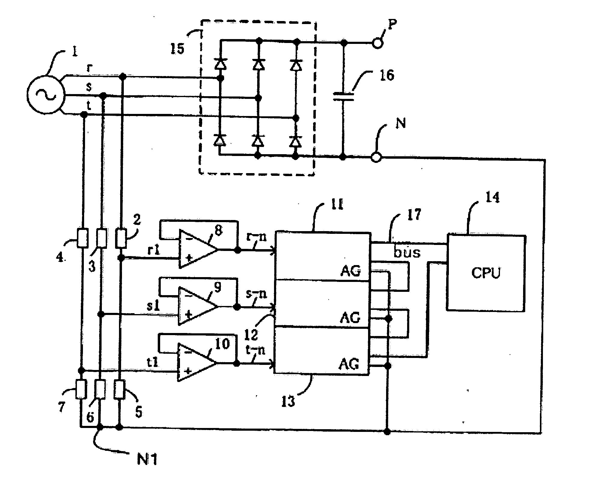
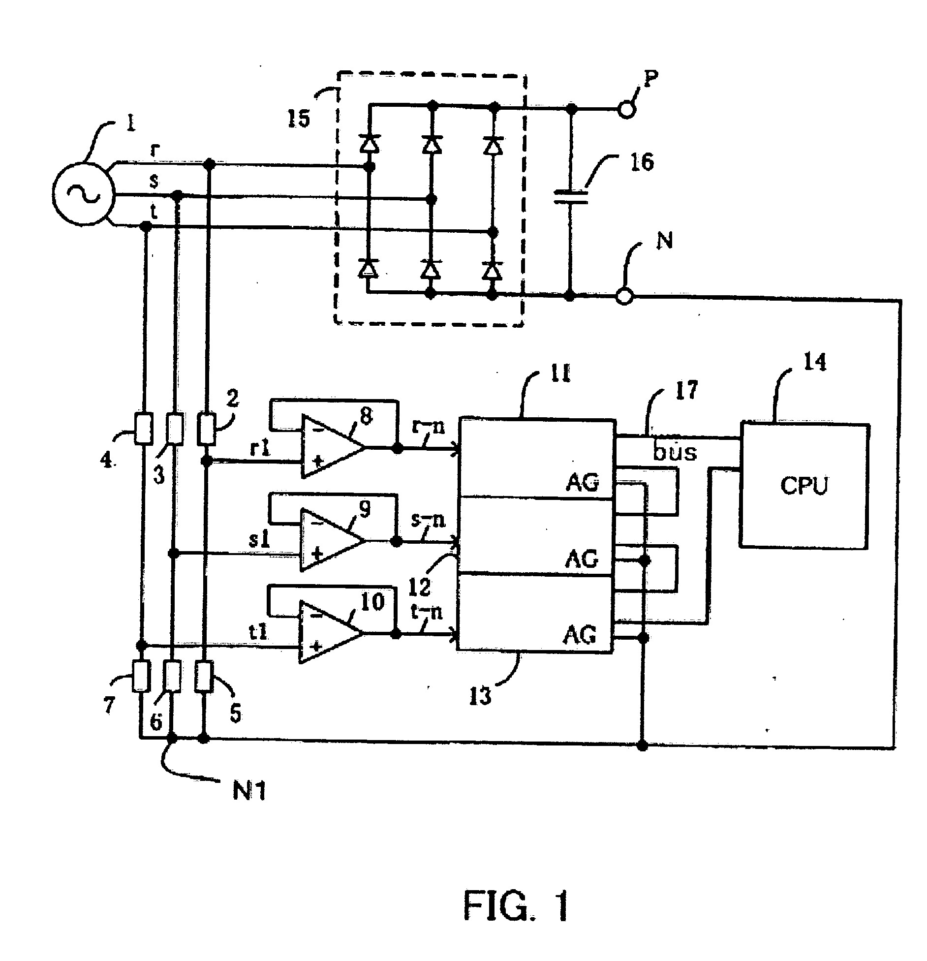
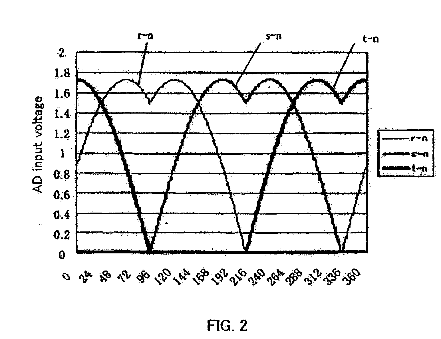
[0040]FIG. 1 shows an embodiment of a three-phase converter according to the method of the present invention, FIG. 2 shows the AD input voltage in a normal status, FIG. 3 shows the AD input voltage in a t-phase-open status, FIG. 4 is the power supply voltage in a normal status, FIG. 5 is the power supply voltage in a t-phase-open status, FIG. 6 shows the line voltage in a normal status, FIG. 7 is the line voltage in a t-phase-open status, FIG. 8 is the voltage of the DC bus line N in a normal status, and FIG. 9 is the voltage of the DC bus line N in a t-phase-open status.

[0041] In FIG. 1, the reference numeral “1” denotes a three-phase AC power supply, the reference numeral “2” denotes a first res...


PUM


Abstract

An open-phase detecting method wherein a simple hardware structure is used to achieve a reduced cost: the IRQ member is reduced to reduce the load on a CPU; the open phase detection is performed in two items, that is, a phase difference and a voltage sign to reduce the possibility of occurrence of erroneous detections; and any phase that is open can be also determined. In the method for detecting any open-phase of the power supply of a three-phase converter, a neutral point N1 is connected to a negative pole side bus N of the DC side output of the rectifying means; an end of the first resistor of each phase, which connects the first resistor to the second resistor of each phase, is connected to an AD converter via a high input impedance means of the respective phase to detect the voltage of the respective phase; the voltage of the respective phase is outputted to a CPU that serves as an open-phase detecting means; and an open phase is detected when the sings of two of the three line voltages determined based on the voltages of the respective phases are different from each other and a phase difference thereof exhibits a half-wave rectification waveform of 180°.

Description

[0001] This application is a continuation-in-part of International Application No. PCT / JP2004 / 10407 filed on Jul. 22, 2004.FIELD OF THE INVENTION [0002] The present invention relates to, for example, a method and an apparatus for detecting an open-phase of a power supply of a three-phase converter. BACKGROUND OF THE INVENTION [0003] The following description sets forth the inventor's knowledge of related art and problems therein and should not be construed as an admission of knowledge in the prior art. [0004] In a conventional method for detecting an open-phase of a power supply of a three phase converter, a logical signal created by comparing a pseudo neutral point of a three-phase AC power source with an input voltage thereof is inputted to a counter to detect the phase difference of each phase. When the phase difference exceeds a predetermined value, it is discriminated that there is an open phase. [0005]FIG. 10 shows a conventional block diagram disclosed by a Japanese Unexamine...

Claims


Application Information

Patent Timeline
IPC IPC(8): G01R31/00G01R19/165G01R19/155G01R29/16G05F1/10H02H3/253H02H3/34
CPCG01R29/16
Inventor HIRAMATSU, KAZUHIKOTAKAHASHI, HAJIME
Owner YASKAWA DENKI KK
Learn More