Back light unit and liquid crystal display device using the same

Inactive Publication Date: 2006-08-24
LG DISPLAY CO LTD
View PDF1 Cites 14 Cited by
  • Summary
  • Abstract
  • Description
  • Claims
  • Application Information

AI Technical Summary

Benefits of technology

[0024] An advantage of the present invention is to provide a back light unit and an LCD device using the same in which currents flowing in a plurality of LEDs are uniformly controlled using an optical sensor and the size of the PCB is reduced.
[0025] Additional advantages and features of the invention will be set forth in part in the description which follows and in part will become apparent to those having ordinary skill in the art upon examination of the following or may be learned from practice of the invention. The advantages of the invention may be realized and attained by the structure particularly pointed out in the written description and claims hereof as well as the appended drawings.
[0026] To achieve these advantages and in accordance with the purpose of the invention, as embodied and broadly described herein, back light unit including a plurality of light emitting diode (LED) arrays, a detector and a driver is disclosed. The LED arrays have a plurality of light emitting diodes (LEDs). The detector detects a feedback

Problems solved by technology

Furthermore, because the related art back light unit 10 having a LED requires a great amount of current, this complicates the line p

Method used


Image

  • Back light unit and liquid crystal display device using the same
  • Back light unit and liquid crystal display device using the same
  • Back light unit and liquid crystal display device using the same

Examples


Embodiment Construction

[0044] Reference will now be made in detail to the embodiments of the present invention, examples of which are illustrated in the accompanying drawings. Wherever possible, the same reference numbers will be used throughout the drawings to refer to the same or like parts.

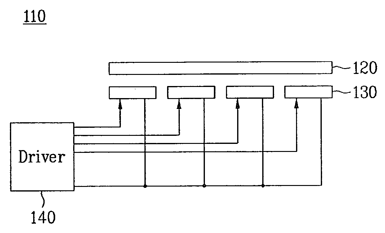
[0045]FIG. 5 illustrates a back light unit having an LED according to an embodiment of the present invention.

[0046] Referring to FIG. 5, the back light unit 110 having an LED according to an embodiment of the present invention includes a plurality of LED arrays 130, a driver 140 for detecting feedback signals corresponding to currents respectively input to the LEDs. The driver 140 uses an optical sensor and drives the LED arrays 130 depending on the detected feedback signals. The back light unit 110 also has a diffusion plate 120 for diffusing light from the LED arrays 130.

[0047] The LED arrays 130, as shown in FIG. 6, include first to Nth LEDs 132 arranged on a PCB 131 where the first to Nth LEDs 132 are parallel...


PUM


Abstract

A back light unit and an LCD device using the same in which current which flows in a plurality of light emitting diodes (LEDs) is uniformly controlled having a small PCB is provided. The back light unit includes a plurality of LED arrays having LEDs and a detector which detects a feedback signal which corresponds to a current that is input to the LEDs. The backlight unit also includes a driver which drives the LEDs in accordance with the feedback signal from the detector.

Description

[0001] This application claims the benefit of the Korean Patent Application No. P2005-14901, filed on Feb. 23, 2005, which is hereby incorporated by reference for all purposes as if fully set forth herein. BACKGROUND OF THE INVENTION [0002] 1. Field of the Invention [0003] The present invention relates to a liquid crystal display (LCD) device, and more particularly, to a back light unit and an LCD device using the same in which current flow in a plurality of light emitting diodes (LEDs) is uniformly controlled using an optical sensor where a size of a printed circuit board (PCB) is reduced. [0004] 2. Discussion of the Related Art [0005] Generally, an LCD device displays desired images on a screen by controlling light transmittance from a back light unit using a liquid crystal panel. The liquid crystal panel includes a plurality of liquid crystal cells having a matrix arrangement and a plurality of control switches switching video signals supplied to the liquid crystal cells. [0006] ...

Claims


Application Information

Patent Timeline
IPC IPC(8): G09G3/36G02F1/133G09G3/20G09G3/34H01L33/00H05B37/02
CPCG09G3/3406G09G2360/145G02F1/1335
Inventor PARK, HEE JEONGCHU, HAANG RHYM
Owner LG DISPLAY CO LTD
Why Eureka
Try Eureka