
Device and method for ejecting ink droplet

a technology of ink droplet and ejection device, which is applied in the direction of printing, other printing apparatus, etc., can solve the problems of insufficient termination, pressure fluctuation, and deterioration of recording quality

Active Publication Date: 2006-08-24
BROTHER KOGYO KK
View PDF4 Cites 7 Cited by
  • Summary
  • Abstract
  • Description
  • Claims
  • Application Information

AI Technical Summary

Benefits of technology

The invention is about an ink droplet ejection device and method that can produce dots of an image on a medium without variation in size between dots or the occurrence of satellite droplets. The device includes a plurality of nozzles, pressure chambers, actuators, and a controller that supplies a control signal to the actuators. The control signal includes a drive pulse train that includes at least two main drive pulses and at least one complementary drive pulse. The at least one complementary drive pulse has a smaller pulse width than the maximizing value to cause ejection of ink droplets that have a smaller volume than the main droplets. The at least one complementary drive pulse can be adjusted to cancel residual pressure waves generated by the main drive pulses. The method involves using the ink droplet ejection device to produce the image on the medium by ejecting the two main ink droplets and the at least one complementary ink droplet that cooperates with them. The difference in the characteristic of ink ejection between devices can cause variation in ejection velocity and volume of the ejected ink droplets. The invention provides a solution to this problem by incorporating the drive pulse train into the control signal for the ink droplet ejection device.

Problems solved by technology

Such pressure fluctuation, in general, cannot be sufficiently terminated upon completion of the successive ejection, so that extra droplets are inevitably ejected as the satellite droplets, due to the pressure fluctuation remaining in the corresponding pressure chamber even after the completion of the successive ejection.
If the satellite droplets are received by the recording medium, it is not possible to obtain a recorded image as desired, resulting in deterioration in the recording quality.
Pressure waves generated by the successive drive pulses remain in the ink stored in the corresponding pressure chamber even after the ink ejection performed by a final one of the successive drive pulses, and the remaining pressure waves cause undesirable ejection of the satellite droplets.
In this sense, the increase in the number of the drive pulses is not feasible.
Further, there is another problem originating from difficulty in equally manufacturing a large number of recording heads without variation among the individual recording heads.

Method used


Image

  • Device and method for ejecting ink droplet
  • Device and method for ejecting ink droplet
  • Device and method for ejecting ink droplet

Examples


Embodiment Construction

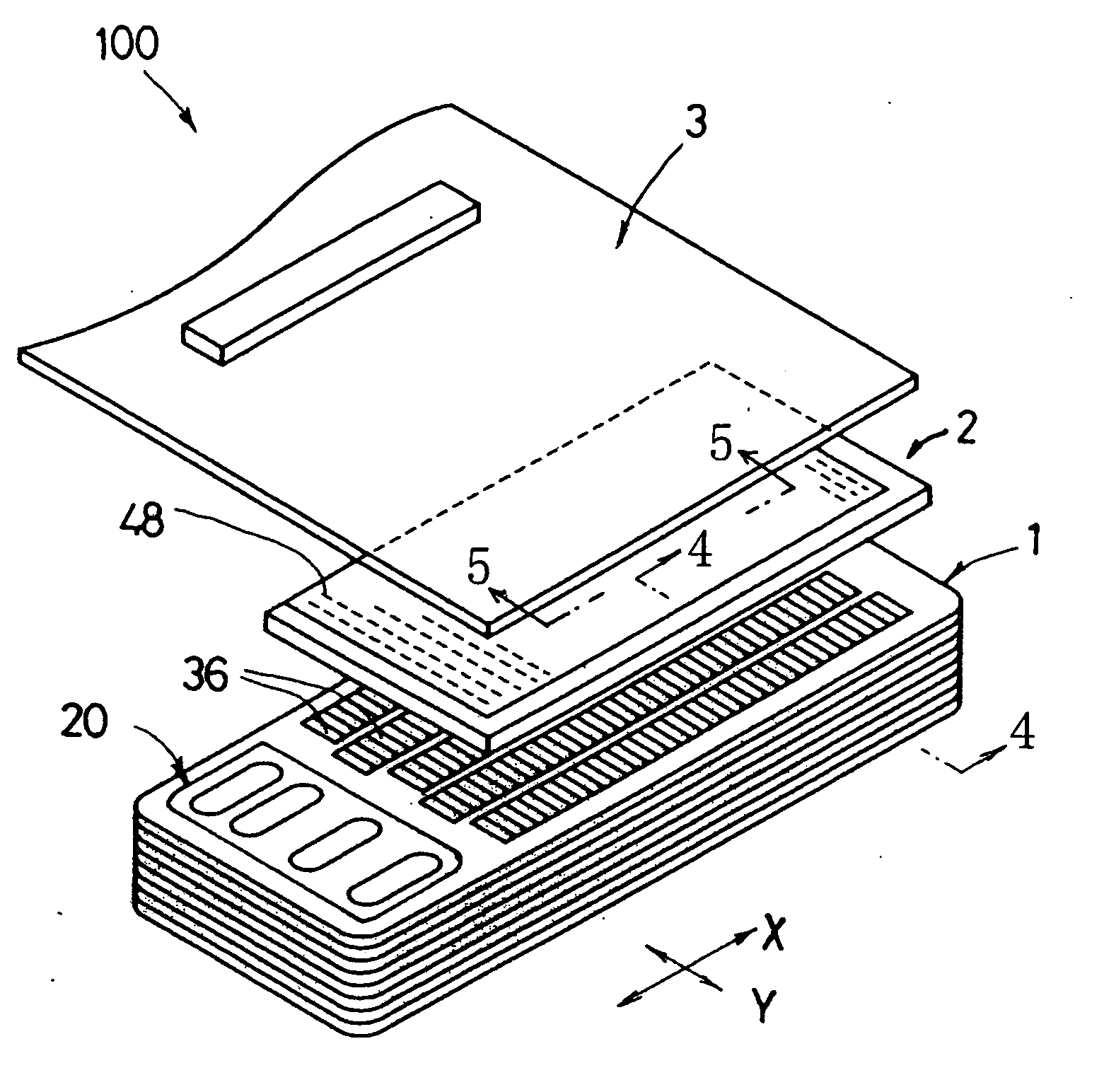
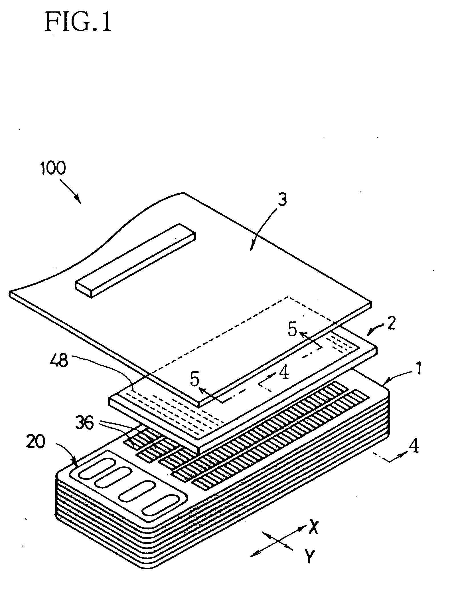
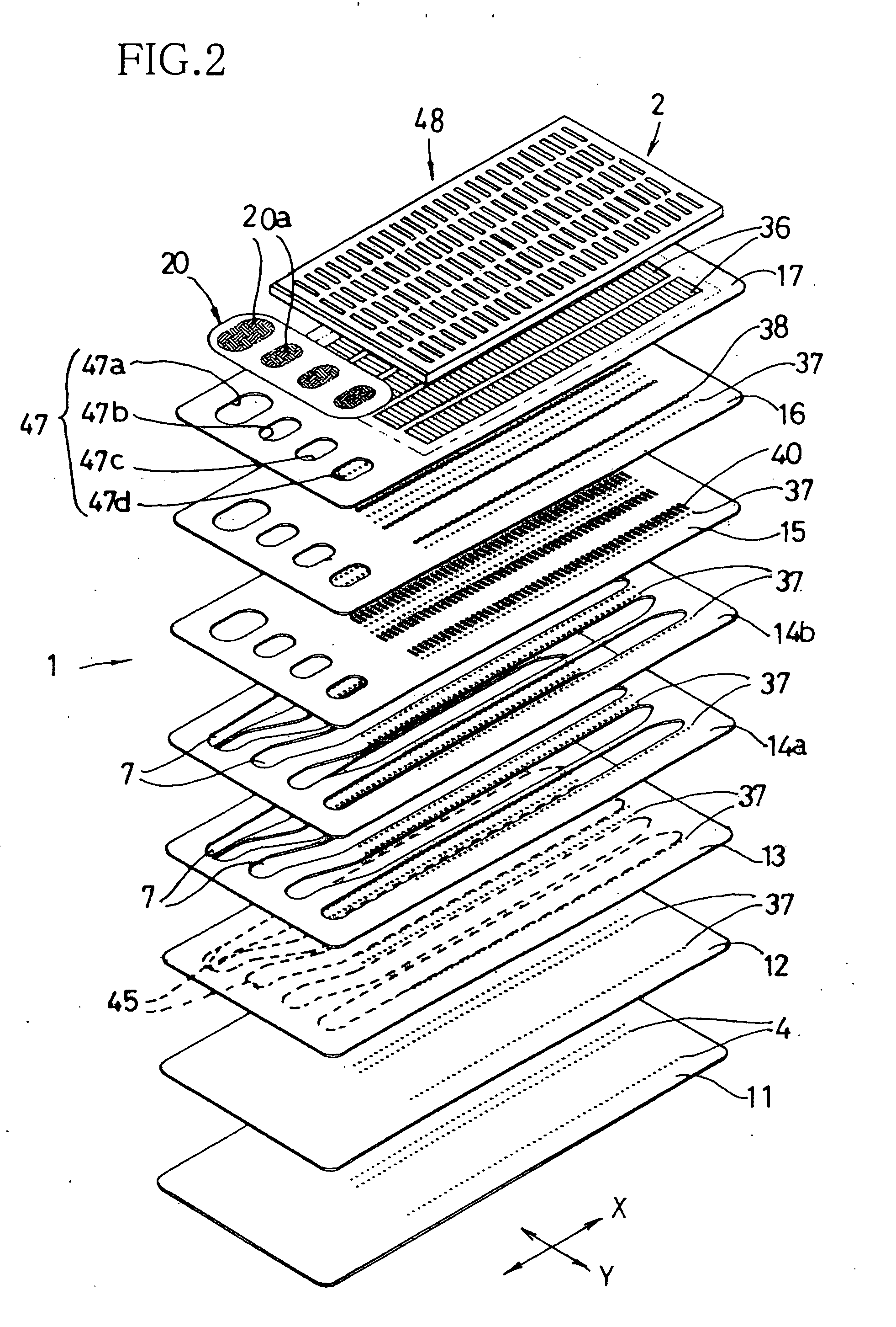
[0039] The present invention is applicable to an ink droplet ejection device such as a recording head (hereinafter referred to as “inkjet head”) 100, as shown in FIG. 1, which is constructed according to the invention. This inkjet head 100 is to be mounted on a carriage (not shown) of an inkjet printer, which is arranged to be reciprocably movable in a main scanning direction that is perpendicular to a sub-scanning direction in which a recording medium is to be fed. The inkjet printer is equipped with ink cartages (not shown) that are removably mounted on the carriage or disposed on a stationary portion of the printer, such that each of inks of four colors (e.g., black, cyan, yellow and magenta) stored in the respective ink cartridges can be supplied directly or through supplying pipes to the inkjet head 100. It is noted that, in the following description, the main scanning direction is referred also to as “second direction” or “X direction” while the sub-scanning direction is refer...


PUM


Abstract

An ink droplet ejection device including: (a) actuators each operable to apply an ejection pressure to an ink stored in a corresponding pressure chamber, for causing an ink ejection through a corresponding nozzle, whereby an image formed as a result of the ink ejection is produced on a medium; and (b) a controller operable to supply a control signal to each actuator, and incorporating a drive pulse train into the control signal for causing ejection of at least two cooperative ink droplets that cooperate to form one dot of the image. The drive pulse train includes at least two drive pulses. One of the at least two drive pulses has a first pulse width smaller than a maximizing value that maximizes an ejection velocity and a volume of each ink droplet to be ejected. Another one of the at least two drive pulses has a second pulse width larger than the maximizing value. Also disclosed a method of producing the image on the medium by using the ink droplet ejection device.

Description

[0001] This application is based on Japanese Patent Application No. 2005-045505 filed in Feb. 22, 2005, the content of which is incorporated hereinto by reference. BACKGROUND OF THE INVENTION [0002] 1. Field of the Invention [0003] The present invention relates to an ink droplet ejection device and an ink droplet ejection method. [0004] 2. Discussion of Related Art [0005] As an ink droplet ejection device, there is known a recording head that is to be incorporated in an inkjet printer. U.S. Pat. No. 6,663,208 (corresponding to JP-2002-160362A) discloses such a recording head including: (a) a cavity unit having (a-1) a plurality of nozzles located in its front portion and (a-2) a plurality of pressure chambers located in its rear portion and held in communication with the respective nozzles; and (b) a piezoelectric actuator unit fixedly disposed on the rear portion of the cavity unit. The piezoelectric actuator unit includes a plurality of deformable portions serving as actuators. Ea...

Claims


Application Information

Patent Timeline
Patent Type & Authority Applications(United States)
IPC IPC(8): B41J2/045
CPCB41J2/04581B41J2/04588B41J2002/14217B41J2002/14225B41J2002/14306B41J2002/14419
Inventor IRIGUCHI, AKIRA
Owner BROTHER KOGYO KK
Learn More