Static eliminator and electric discharge module

Active Publication Date: 2006-08-24
KOGANEI +1
View PDF14 Cites 15 Cited by
  • Summary
  • Abstract
  • Description
  • Claims
  • Application Information

AI Technical Summary

Benefits of technology

[0018] According to the present invention, the electric discharge module detachably mounted to the boss portion disposed at a center portion of the air guiding member having the opposite electrode has the holder detachable/attachable from/to the boss portion and the discharge electrodes attached to the holder, so that in maintenance of the discharge electrodes, the electric discharge module can be easily detached from the boss portion. Furthermore, even when the electric discharge module is replaced, the module can be easily detached. In being detached, the electric discharge

Problems solved by technology

In the case of manufacturing and assembling the electronic components, if static electricity is charged in jigs etc. for manufacturing and assembling the electronic components, foreign substances such as dust adhere to the electronic components etc. and defective goods are produced

Method used


Image

  • Static eliminator and electric discharge module
  • Static eliminator and electric discharge module
  • Static eliminator and electric discharge module

Examples


Example

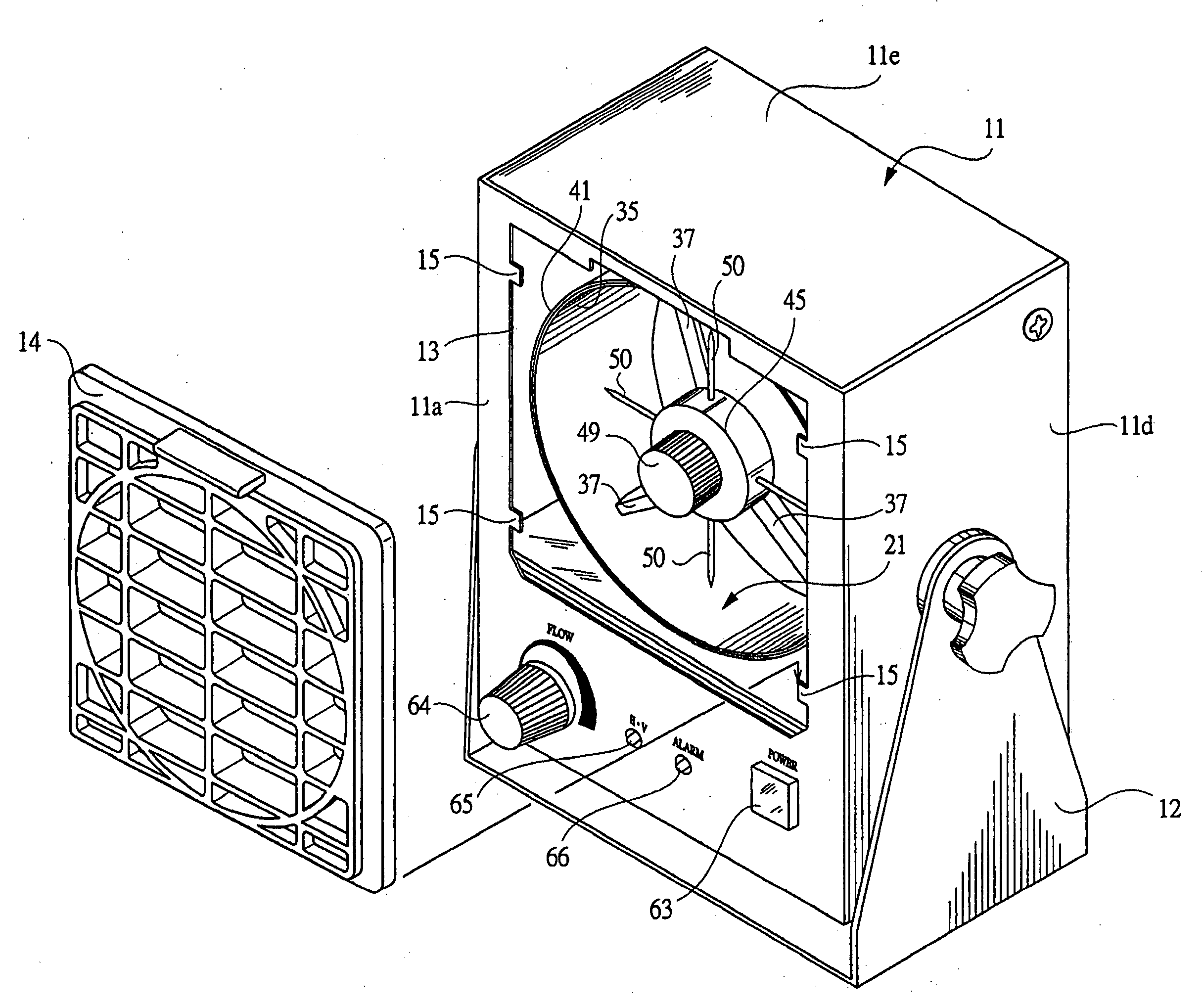
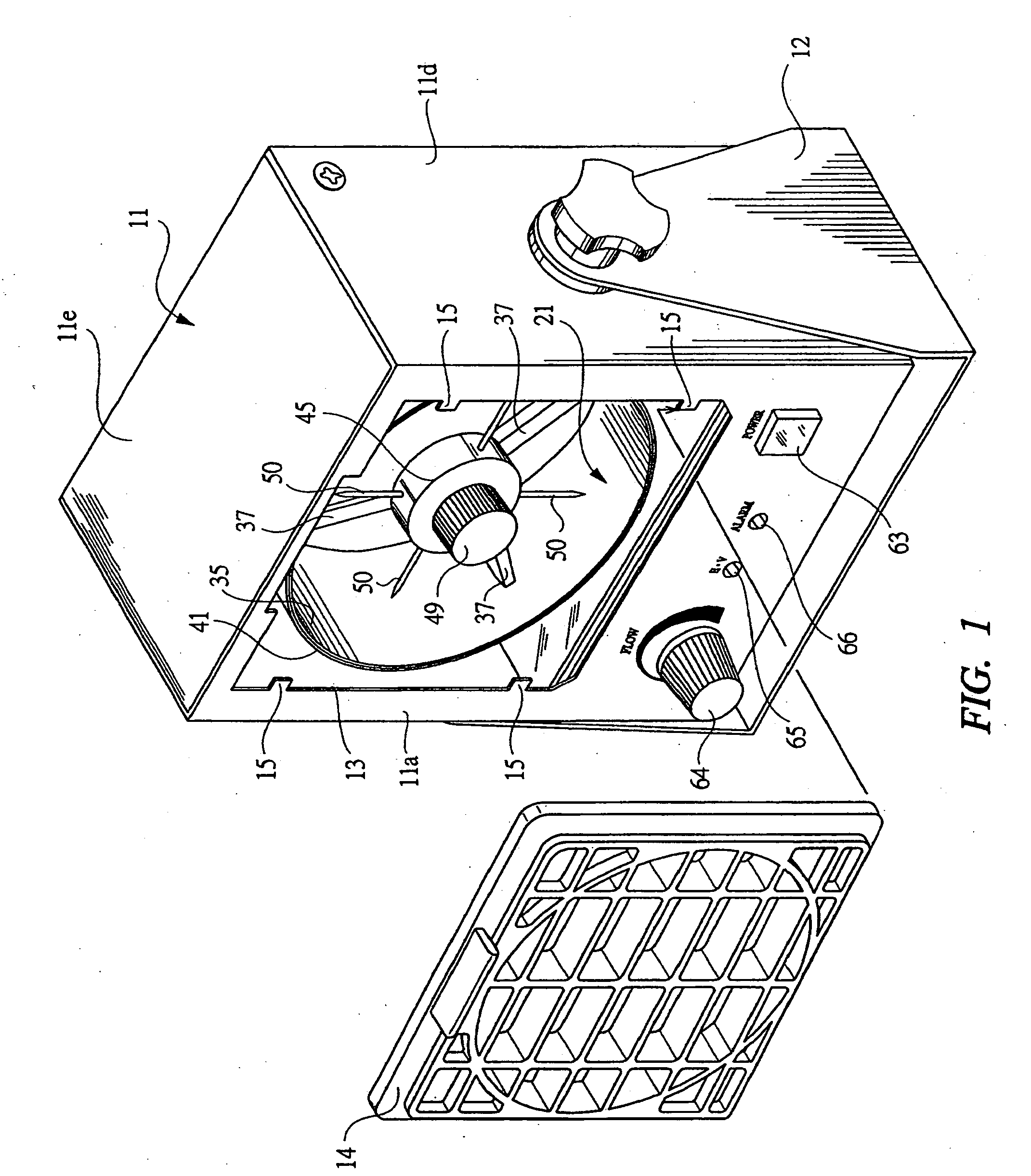
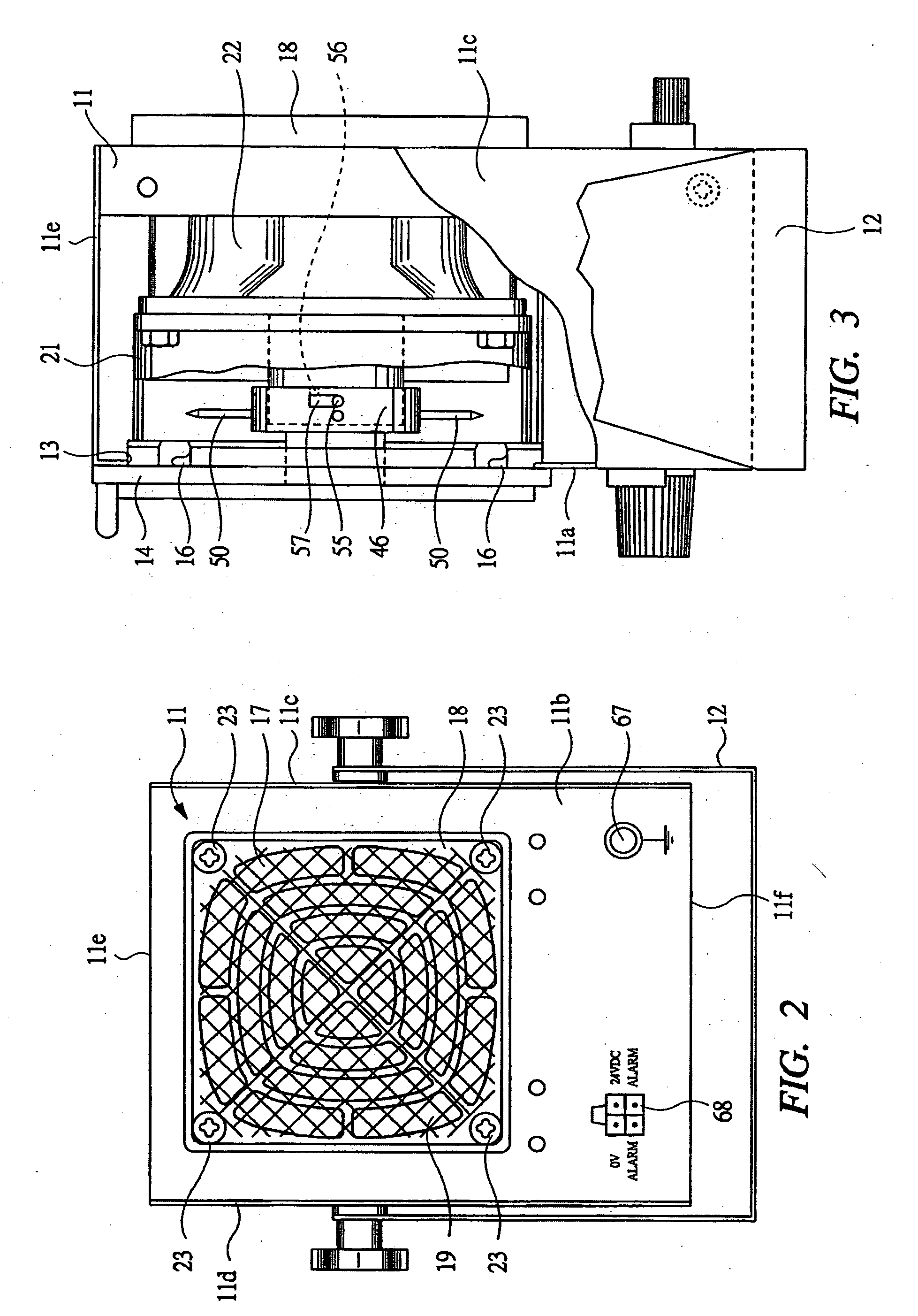
[0035] Hereinafter, embodiments according to the present invention will be detailed based on the drawings. FIG. 1 is a perspective view showing a front side of a static eliminator according to one embodiment of the present invention; FIG. 2 is a rear view of the static eliminator shown in FIG. 1; and FIG. 3 is a partially-sectioned side view of the static eliminator shown in FIG. 1.

[0036] A static eliminator includes a case body 11 formed into an approximately rectangular parallelepiped as a whole. The case body 11 has a front wall 11a, a back wall 11b, left and right sidewalls 11c and 11d, a top wall 11e, and a bottom wall 11f. The case body 11 is configured by combining a member integrally formed with the front wall 11a and the left and right sidewalls 11c and 11d and a member integrally formed with the back wall 11b, the top wall 11e, and the bottom wall 11f. A stand 12 is attached to the case body 11, so that the static eliminator is installed by the stand 12 at positions for u...


PUM


Abstract

A static eliminator capable of replacing a discharge needle and improving maintainability of the eliminator is disclosed. The static eliminator comprises: an air-guiding duct having a tubular portion provided with an opposite electrode and a boss portion; and an electric discharge module detachably mounted on the tubular portion, wherein ionized air is supplied to the air-guiding duct by a fan of an air blower. The electric discharge module has a holder fitted in a boss portion and a plurality of discharge electrodes attached to the holder so as to protrude toward the opposite electrode in an outer-radial direction. When foreign substances or the like adhere to a tip of the discharge electrode or when the discharge electrode deteriorates, the electric discharge module is detached from the boss portion.

Description

CROSS-REFERENCED TO RELATED APPLICATIONS [0001] Applicant hereby claims foreign priority benefits under U.S.C. § 119 from Japanese Patent Application No. 2005-8567 filed on Jan. 17, 2005, the contents of which are incorporated by reference herein. BACKGROUND OF THE INVENTION [0002] The present invention relates to a static eliminator and an electric discharge module for eliminating static electricity from an object to be processed such as an electronic component charged with static electricity. [0003] In the case of manufacturing and assembling the electronic components, if static electricity is charged in jigs etc. for manufacturing and assembling the electronic components, foreign substances such as dust adhere to the electronic components etc. and defective goods are produced, whereby the electronic components during a transfer process are mutually attracted and contact with each other and cannot be transferred smoothly. Therefore, a static eliminator also called an ionizer or io...

Claims


Application Information

Patent Timeline
IPC IPC(8): H02H9/00H05F3/04H01T23/00H05F3/00
CPCH01T23/00H05F3/04G04G13/02G06M1/083G06M1/272G06M3/00
Inventor ONEZAWA, KAZUYOSHIFUKADA, YOSHINARIENOMOTO, YOSUKE
Owner KOGANEI
Why Eureka
Try Eureka