
Methods and systems for communicating data through a pipe

Inactive Publication Date: 2006-08-24
CHARLES STARK DRAPER LABORATORY
View PDF29 Cites 43 Cited by
  • Summary
  • Abstract
  • Description
  • Claims
  • Application Information

AI Technical Summary

Benefits of technology

[0011] The present invention greatly improves the rate and range of data transmission, as well as the reliability of an acoustic telemetry system, by employing broadband, as opposed to narrowband, acoustic wave propagation through a drill string or pipe. By transmitting multiple sets of data simultaneously at different frequencies, the effective rate of the data transmission and the range of the acoustic telemetry system are increased. For example, certain embodiments of the acoustic telemetry system of the present invention are capable of providing a data rate of better than 1000 bits / second at 6000 feet, and better than 10 bits / second out to 20,000 feet.

Problems solved by technology

In addition, the mud pulse technique requires a pressurized drill string, which limits the drill string's applicability.
Poor drilling performance may also result.
Both of these methods have, however, disadvantages associated with signal attenuation, ambient noise, high temperatures, and compatibility with standard drilling procedures.
Disadvantages of this approach, however, include a data rate that is limited to 8 bits / second and a communication range that is effectively limited to 6000 feet.
In addition, these acoustic telemetry systems do not operate while drilling is in progress.
When they do operate, communication is only unidirectional.
Another disadvantage is that characterization and sorting of tubing is often required.
Disadvantages of this approach also include a data rate that is limited to 8 bits / second and a communication range that is effectively limited to 6000 feet.
A telemetry system based on narrowband amplitude key modulation also does not operate while drilling is in progress, and, when it does operate, communication is only unidirectional.
Another disadvantage is that calibration is required prior to each transmission.

Method used


Image

  • Methods and systems for communicating data through a pipe
  • Methods and systems for communicating data through a pipe
  • Methods and systems for communicating data through a pipe

Examples


Embodiment Construction

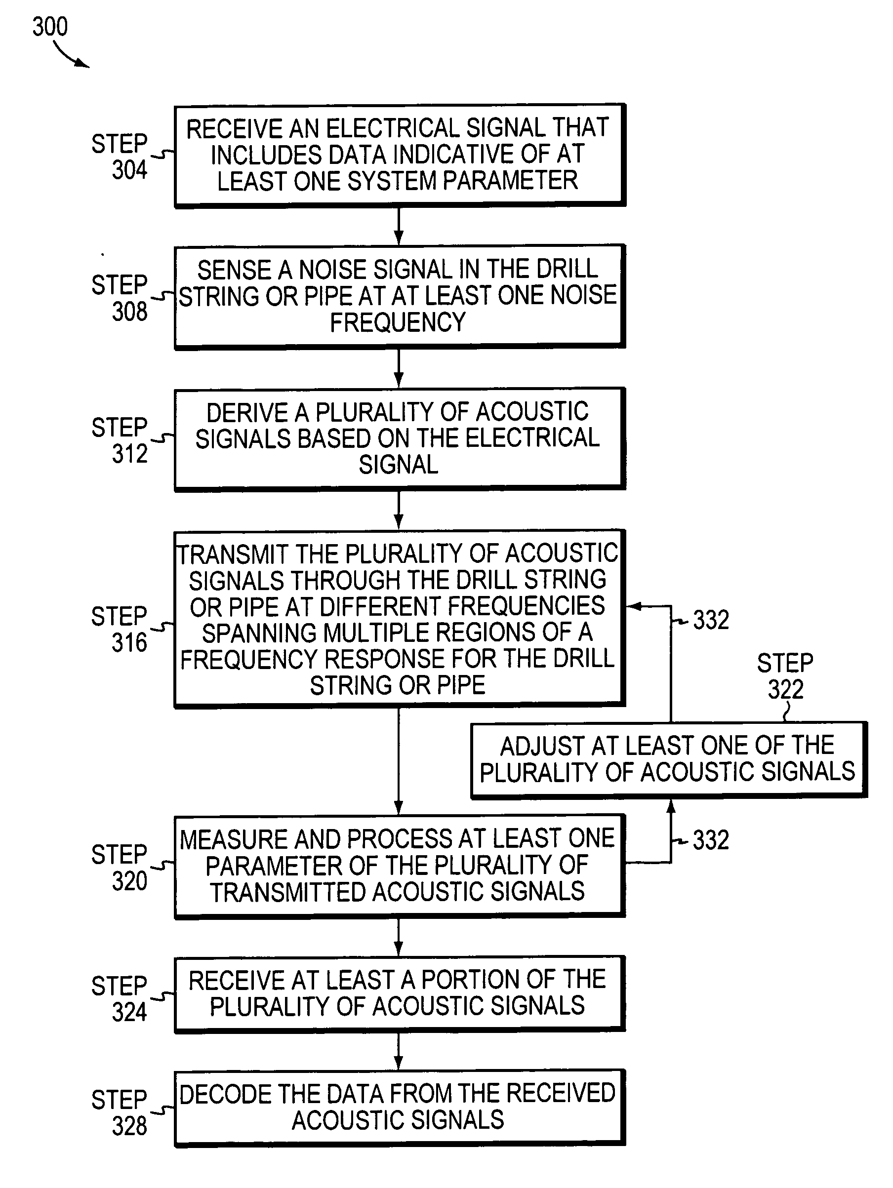
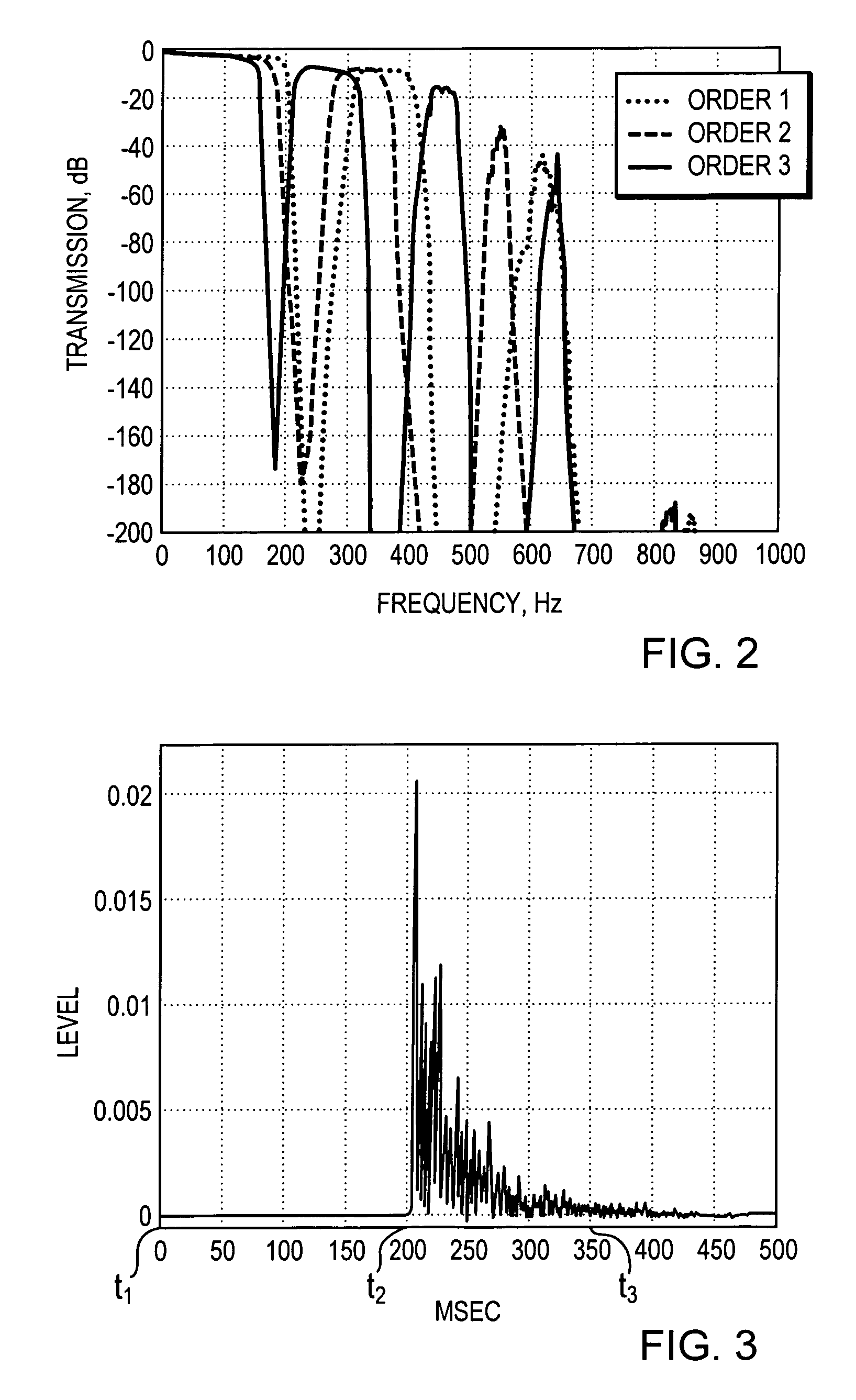
[0035] In broad overview, the present invention counteracts the effects of time-spreading and reduces the likelihood that data is lost or corrupted because an acoustic signal is transmitted through a drill string at a frequency corresponding to a null in the frequency domain. For example, in various embodiments, the present invention employs broadband, as opposed to narrowband, communication techniques, desirably with redundancy, to acoustically transmit data through a drill string or pipe. More specifically, in some embodiments of the invention, a plurality of acoustic signals, some of which contain the same (i.e., redundant) information, or portions of information, as other acoustic signals, are transmitted through the drill string or pipe substantially simultaneously at different frequencies spanning multiple regions of a frequency response for the drill string or pipe. In such a fashion, the likelihood of receiving complete, and correct, data at the opposite end of the drill str...


PUM


Abstract

An acoustic telemetry system includes a piezoelectric stack at least partially disposed within a segment of pipe, and electrical circuitry for controlling the piezoelectric stack. In response to a signal from the electrical circuitry, the piezoelectric stack generates a plurality of acoustic signals for transmission through the pipe at different frequencies spanning multiple regions of a frequency response for the pipe.

Description

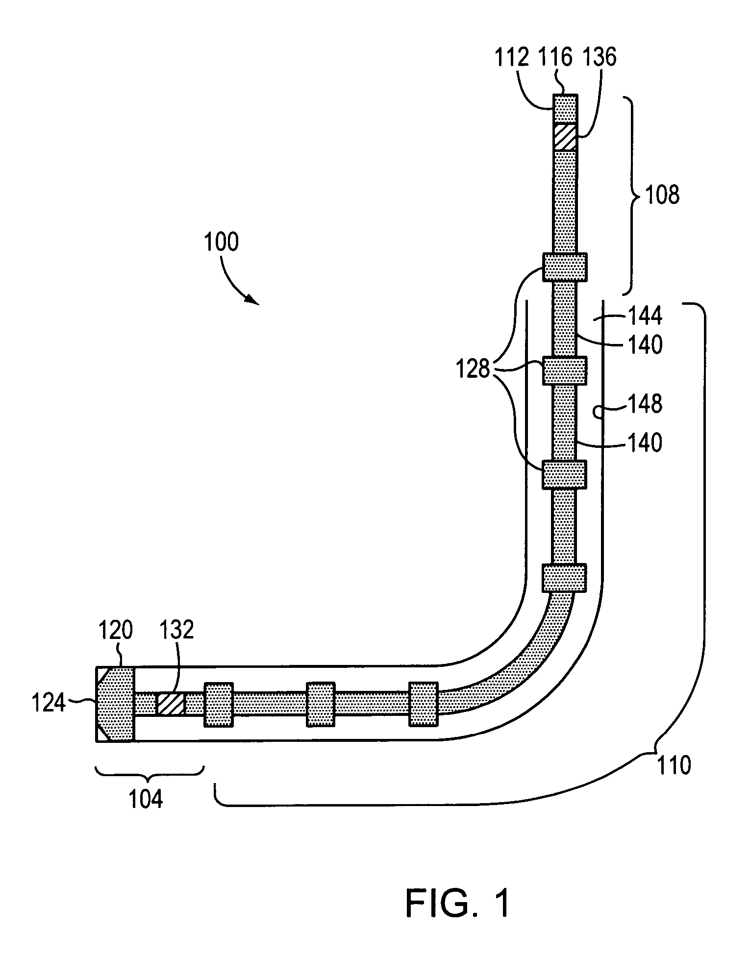
CROSS-REFERENCE TO RELATED APPLICATION [0001] This application claims priority to and the benefit of, and incorporates herein by reference in its entirety, U.S. Provisional Patent Application Ser. No. 60 / 656,030, which was filed on Feb. 24, 2005.TECHNICAL FIELD [0002] The present invention generally relates to data communication. More particularly, the invention relates to methods and systems for acoustically communicating data through a pipe. BACKGROUND [0003] Wells of the type commonly used for petroleum or geothermal exploration are often on the order of 1.5 miles deep. Typically, these wells or “boreholes” are drilled using pipes (also referred to as “drill strings”) assembled from relatively light metal sections connected end-to-end by tooling joints. These sections are generally about 30 to 45 feet long. To form a borehole, the drill string is rotated such that a drill bit attached to its “downhole” or operative end bites into the earth. Additional sections are typically added...

Claims


Application Information

Patent Timeline
IPC IPC(8): H04H9/00H04H60/31
CPCE21B47/16
Inventor TINGLEY, ROBERT D.
Owner CHARLES STARK DRAPER LABORATORY
Learn More