Pattern diversity to support a MIMO communications system and associated methods

a technology of mimo communication system and pattern diversity, applied in the field of communication system, can solve the problems affecting the reception of signals, and affecting the use of direction finders using radio waves, etc., and achieve the effect of reducing the number of antenna elements

Inactive Publication Date: 2006-08-24
INTERDIGITAL TECH CORP
View PDF6 Cites 52 Cited by
  • Summary
  • Abstract
  • Description
  • Claims
  • Application Information

AI Technical Summary

Benefits of technology

[0012] In view of the foregoing background, it is therefore an object of the present invention to reduce the number of antenna elements at a MIMO receiver as compared to the number of antenna elements at a MIMO transmitter while still providing a robust MIMO communications system.

Problems solved by technology

The problem with such an implementation is that the performance of a MIMO communications system is usually proportional to the number of antenna elements used.
When a MIMO receiver is implemented within a small portable communications device, there is little available volume for a large number of antenna elements, and mounting the antenna elements on the outside of the communications devices is a problem for the user.
In addition, if two or more received signals are close together in angular distance, generation of different antenna patterns by the MIMO receiver may not be adequate to determine differences in the received signals.
Even if beam forming is used, making the beam sufficiently narrow or the bore sight adjustable may not be practical or cost effective.

Method used


Image

  • Pattern diversity to support a MIMO communications system and associated methods
  • Pattern diversity to support a MIMO communications system and associated methods
  • Pattern diversity to support a MIMO communications system and associated methods

Examples


Embodiment Construction

[0034] The present invention will now be described more fully hereinafter with reference to the accompanying drawings, in which preferred embodiments of the invention are shown. This invention may, however, be embodied in many different forms and should not be construed as limited to the embodiments set forth herein. Rather, these embodiments are provided so that this disclosure will be thorough and complete, and will fully convey the scope of the invention to those skilled in the art. Like numbers refer to like elements throughout.

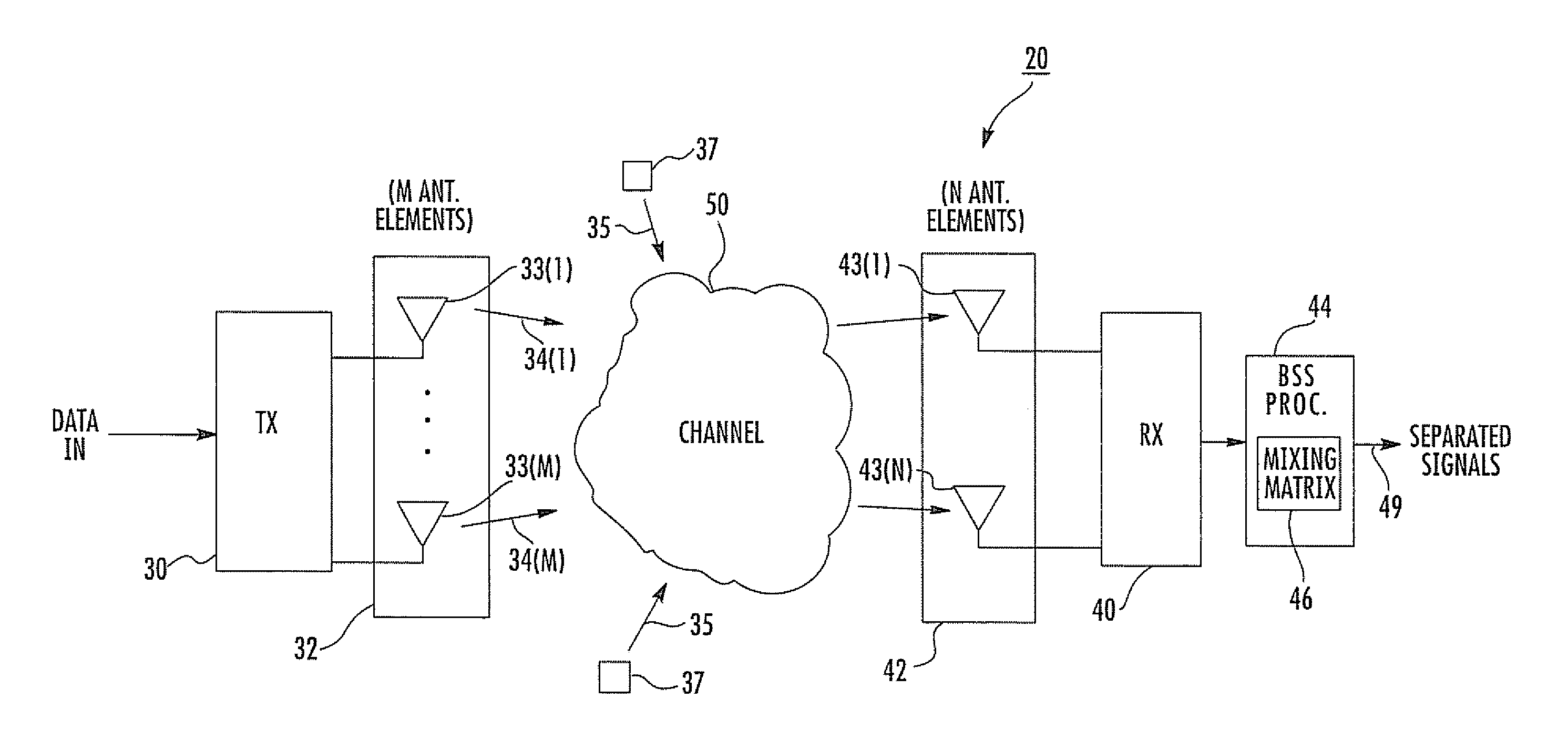
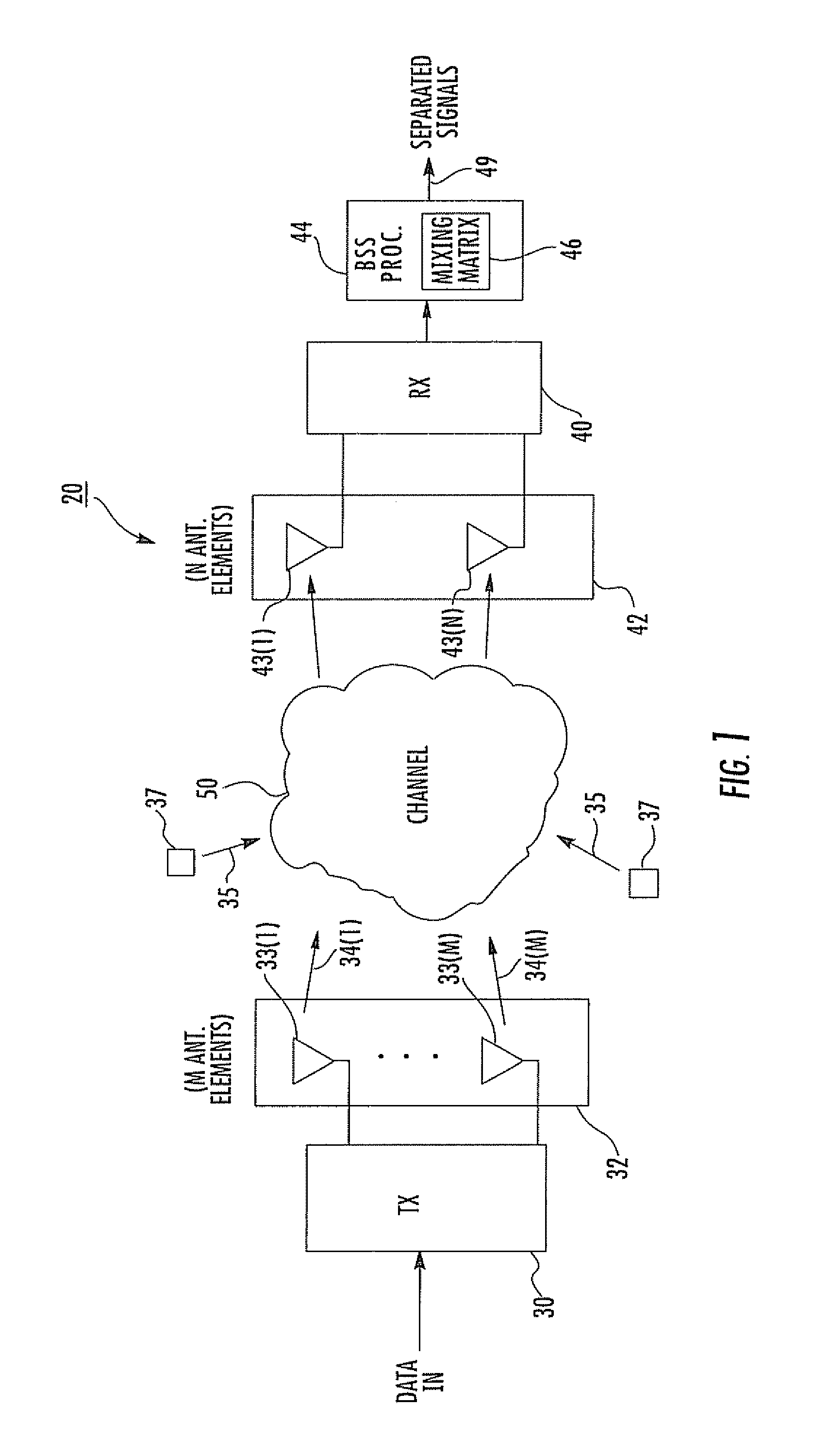
[0035] Referring initially to FIG. 1, a MIMO communications system 20 will now be described. The MIMO communications system 20 comprises a transmitter 30, a transmit antenna array 32, a receiver 40 and a receive antenna array 42. As readily appreciated by those skilled in the art, the transmitter 30 and receiver 30 may be replaced with transceivers. Consequently, their respective antenna arrays 32, 42 support two-way data exchanges. However, for purposes...


PUM


Abstract

A MIMO communications system includes a transmitter, and a receiver synchronized with the transmitter. The transmitter changes the power levels for each layered space data stream on a time slotted basis. The data streams arrive at the receiver with various power levels, which provides suitable differences in the received signals for population of a mixing matrix for signal separation processing.

Description

RELATED APPLICATION [0001] The present application is a continuation-in-part of U.S. patent application Ser. No. 11 / 232,610 filed Sep. 22, 2005 which claims the benefit of U.S. Provisional Application Ser. No. 60 / 642,941 filed Jan. 11, 2005; No. 60 / 639,223 filed Dec. 23, 2004; No. 60 / 621,113 filed Oct. 22, 2004; No. 60 / 620,775 filed Oct. 20, 2004; No. 60 / 620,776 filed Oct. 20, 2004; No. 60 / 620,862 filed Oct. 20, 2004; No. 60 / 615,338 filed Oct. 1, 2004; No. 60 / 615,260 filed Oct. 1, 2004; No. 60 / 612,546 filed Sep. 23, 2004; No. 60 / 612,435 filed Sep. 23, 2004; No. 60 / 612,433 filed Sep. 23, 2004; No. 60 / 612,550 filed Sep. 23, 2004; No. 60 / 612,632 filed Sep. 23, 2004; No. 60 / 612,548 filed Sep. 23, 2004; No. 60 / 612,471 filed Sep. 23, 2004; No. 60 / 612,551 filed Sep. 23, 2004; No. 60 / 612,469 filed Sep. 23, 2004; and No. 60 / 612,547 filed Sep. 23, 2004 the entire contents of which are incorporated herein by reference.FIELD OF THE INVENTION [0002] The present invention relates to the field of ...

Claims


Application Information

Patent Timeline
Patent Type & Authority Applications(United States)
IPC IPC(8): H04B1/02H04B7/08H04M1/00H04J99/00
CPCH04B7/0413H04B7/10H04W52/42H04B7/0842H04L1/0038H04L1/02
Inventor GOLDBERG, STEVEN J.
Owner INTERDIGITAL TECH CORP
Why Eureka
Try Eureka