Graft anchor

a technology for securing tendons and tendons, applied in the field of medical devices, can solve the problems of tibial graft fixation, surgical failure, slippage of graft past the interference screw, etc., and achieve the effect of preventing graft migration, facilitating grouping of ends, and increasing volum

Inactive Publication Date: 2006-08-24
BICKLEY BARRY T
View PDF2 Cites 132 Cited by
  • Summary
  • Abstract
  • Description
  • Claims
  • Application Information

AI Technical Summary

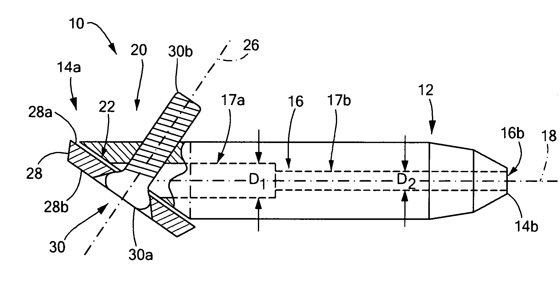
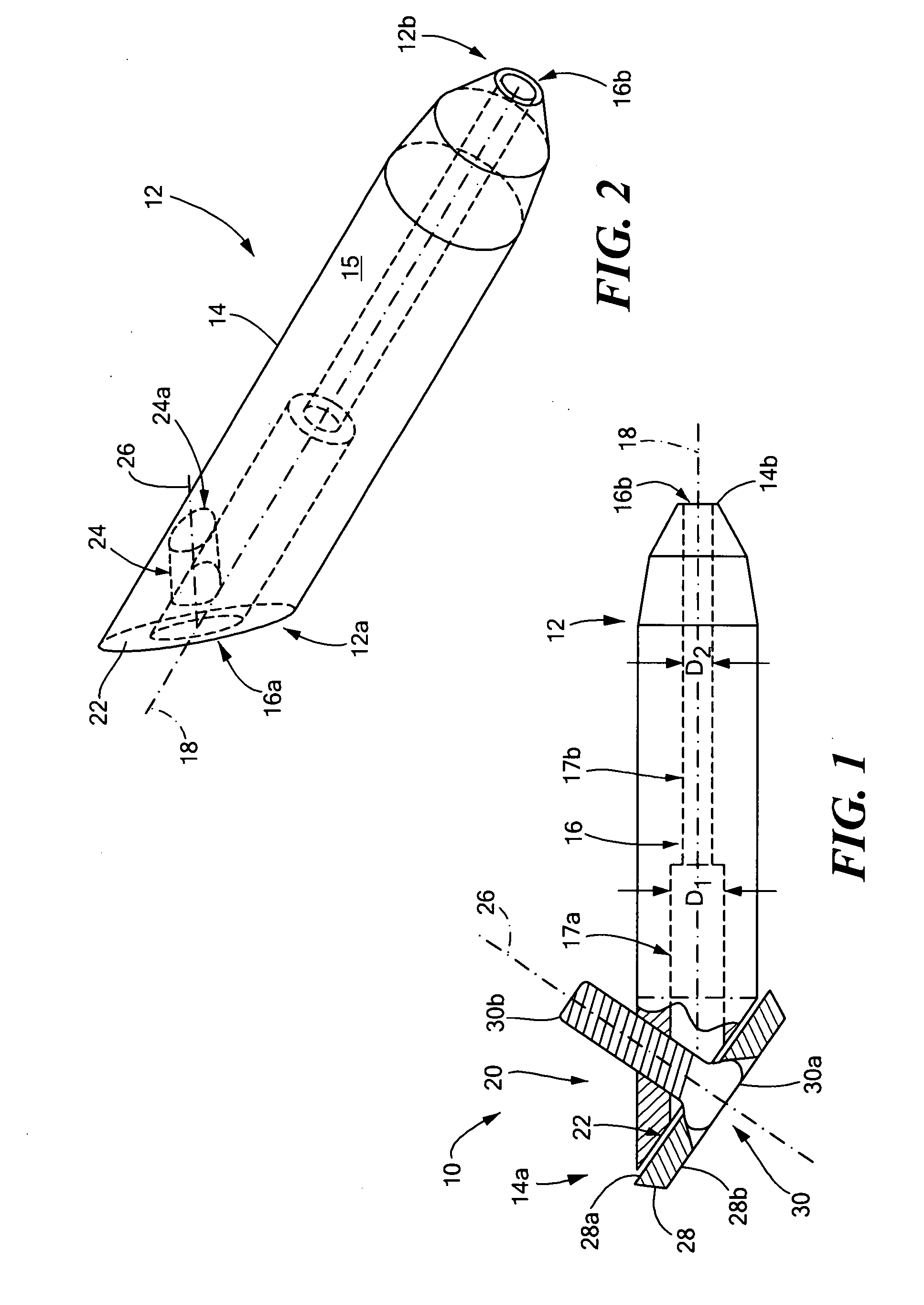
Benefits of technology

[0010] With this particular arrangement, an easy-to-use graft anchor which provides a large amount of graft holding power is provided. By using both an interference screw and a cross member disposed in the interference screw, two approaches for securing grafts are combined into a single device thereby providing a single device having a graft holding power which is increased compared with the holding power of prior art devices. The device can be used with all standard grafts commonly used for ACL knee reconstruction as well as with grafts used in other types of reconstructions or other applications.
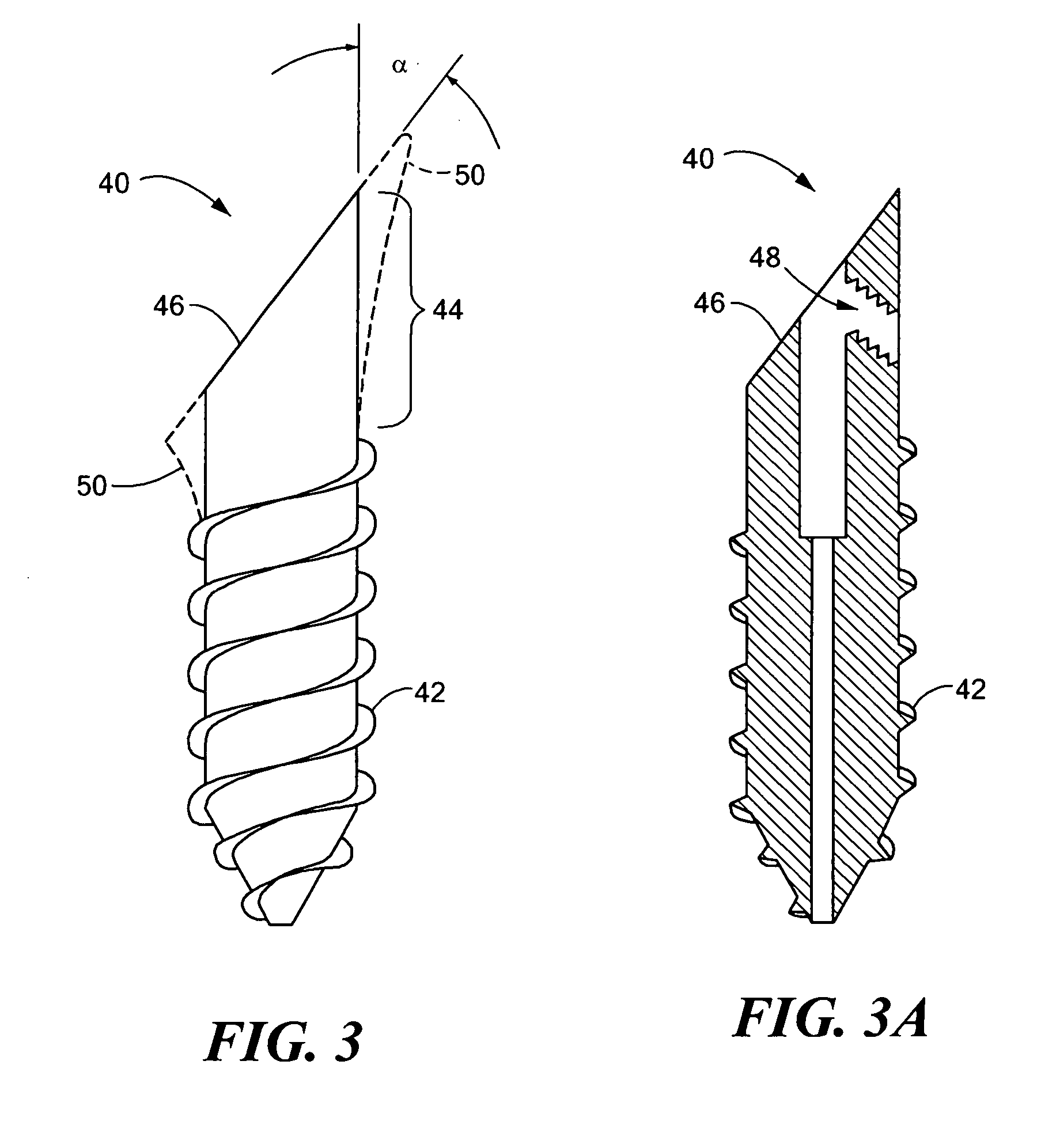
[0011] The interference screw is cannulated to follow a pre-placed guide wire. In one embodiment, the screw is not fully threaded on its outer surface but rather has a non-threaded portion in a head region of the screw. This head region can be slightly flared in diameter for the purpose of taking up a greater volume within a hole provided in an outer cortex of the bone which accepts the interference screw. The end of the head is preferably provided having an angle selected to such that the screw head is less prominent from a surface of a bone into which the interference screw is inserted. When the screw is placed obliquely into the bone as is commonly done in ligament reconstruction surgery, head angle is approximately forty-five degrees. A portion of the head can be beveled to accommodate grafts (e.g. tendons or other types of grafts) as they are drawn over the angled face of the head and secured. This bevel can be further grooved longitudinally to facilitate grouping of ends of the grafts together and preventing migration of the grafts during placement of a washer. The interference screw accommodates a cross member which secures the grafts. In one embodiment, the cross member is provided as a screw and the interference screw includes a threaded screw hole which accepts the cross screw. In one embodiment, a central longitudinal axis of the screw hole is provided at an angle which is perpendicular to the angled face.
[0012] In one embodiment, the cross member secures a graft in a desired location. In another embodiment, the cross member is in conjunction with a washer. The washer can be provided having a circular, elliptical or any other geometric shape. In one embodiment, the cross member secures the washer and the washer compresses the grafts (e.g. tendon(s)) that are placed over the angled face of the interference screw. The washer can also be provided having a complex shape that helps to minimize prominence above a surface of a bone in which the interference screw is disposed. For example, the washer may be provided having rounded edges and a generally rounded external side while maintaining a generally flat internal side that is disposed against the angled-face of the interference screw.
[0014] Both the angled face of the interference screw and the under surface of the washer may be textured or grooved. This facilitates keeping the graft ends gathered in place once the graft ends are arranged between the angled face of the interference screw and a surface of the cross-member or washer (in the case where a washer is used to help secure the grafts in place). The textured or grooved surfaces also increase frictional resistance to forces which may pull the graft ends from beneath the cross member (or washer).

Problems solved by technology

Graft fixation on the tibial side remains a source of difficulty and surgical failures.
Such an injury frequently results in knee instability that requires surgical reconstruction of the ACL in order to return to athletic activity and in many cases to even return to normal daily activities.
Failure of this technique can still result from slippage of the graft past the interference screw.
In pullout studies, this is a frequent failure mode of this type of fixation.
Hamstring and soft tissue grafts have had some difficulty in regard to fixation of the graft to the bone, in particular on the tibial side of the knee.
The problem lies in the fact that the bone where the tunnel is made is often soft in this portion of the tibia.
This can compromise any method of fixation that relies on compression against this weak bone.

Method used


Image

  • Graft anchor
  • Graft anchor
  • Graft anchor

Examples


Embodiment Construction

[0027] Before describing exemplary embodiments of graft anchors and elements thereof as shown in FIGS. 1-6, it should be appreciated that description herein below is of exemplary embodiments only and is not intended to limit the scope, applicability or configuration of the claimed invention in any way. Rather, the following description provides a convenient illustration for implementing exemplary embodiments of the invention. Various changes to the described embodiments may be made in the function and arrangement of the elements described without departing from the spirit and scope of the invention as set forth in the appended claims.

[0028] It should also be appreciated that reference is made herein to “graft ligaments” or more simply “grafts” and that for the purposes of the present invention it should be understood that reference herein to “grafts” includes but is not limited to a ligament or tendon which is harvested from elsewhere in a patient (or from outside the patient) as w...


PUM


Abstract

A graft anchor includes an interference screw having a passage provided therein and a cross member adapted to be disposed in the passage of the interference screw to secure a graft.

Description

CROSS-REFERENCE TO RELATED PATENT APPLICATIONS [0001] This patent application claims the benefit of U.S. provisional application No. 60 / 642,889 filed on Jan. 11, 2006 under 35 U.S.C. §119(e).GOVERNMENT RIGHTS [0002] Not applicable. TECHNICAL FIELD [0003] The invention generally relates to medical devices and more particularly to methods and apparatus for securing tendons. BACKGROUND OF THE INVENTION [0004] As is known in the art, injuries to the anterior cruciate ligament (ACL) of the knee are common in athletically active individuals. Graft fixation on the tibial side remains a source of difficulty and surgical failures. The limiting of tension loss and laxity depends upon fixation and bone quality. [0005] As is known, the anterior cruciate ligament (ACL) is commonly injured in athletically active individuals. Such an injury frequently results in knee instability that requires surgical reconstruction of the ACL in order to return to athletic activity and in many cases to even retur...

Claims


Application Information

Patent Timeline
Patent Type & Authority Applications(United States)
IPC IPC(8): A61B17/58
CPCA61B17/864A61B17/8645A61F2/0811A61F2002/0829A61F2002/0841A61F2002/0858A61F2002/0882
Inventor BICKLEY, BARRY T.
Owner BICKLEY BARRY T
Why Eureka
Try Eureka