Runoff rain gauge

Inactive Publication Date: 2006-08-31
NOE STEPHEN A
View PDF10 Cites 18 Cited by
  • Summary
  • Abstract
  • Description
  • Claims
  • Application Information

AI Technical Summary

Benefits of technology

[0022] Another embodiment includes an alternate mounting system for the runoff rain gauge wherein a collector tube containing a previously extracted core sample is directly coupled to the ground such that the bottom core surface and top ground surface are in direct contact. This configuration allows the runoff measurement system to be positioned above grade, thereby allowing runoff drainage to grade, while also effectively providing the accuracy of an extended core sample. The ground-coupled de

Problems solved by technology

However, the prior art rain gauges fail to take into account how much water has run off from the soil, and how much has soaked in.
Of course, the rainfall that runs off serves no benefit in irrigation for crops or other plant growth.
Whenever the precipitation rate exceeds the infiltration rate, excess water

Method used


Image

  • Runoff rain gauge
  • Runoff rain gauge
  • Runoff rain gauge

Examples


Embodiment Construction

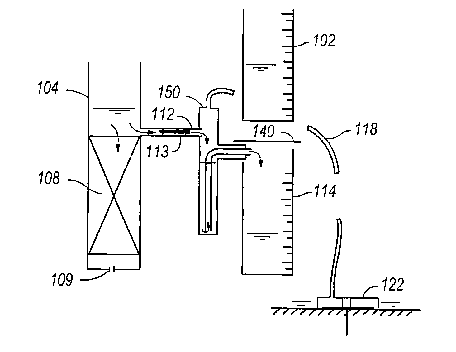
[0041] The present invention provides a precipitation measuring device capable of simultaneously measuring rainfall and soil runoff during a rain event. Soil infiltration is thereby determined by difference.

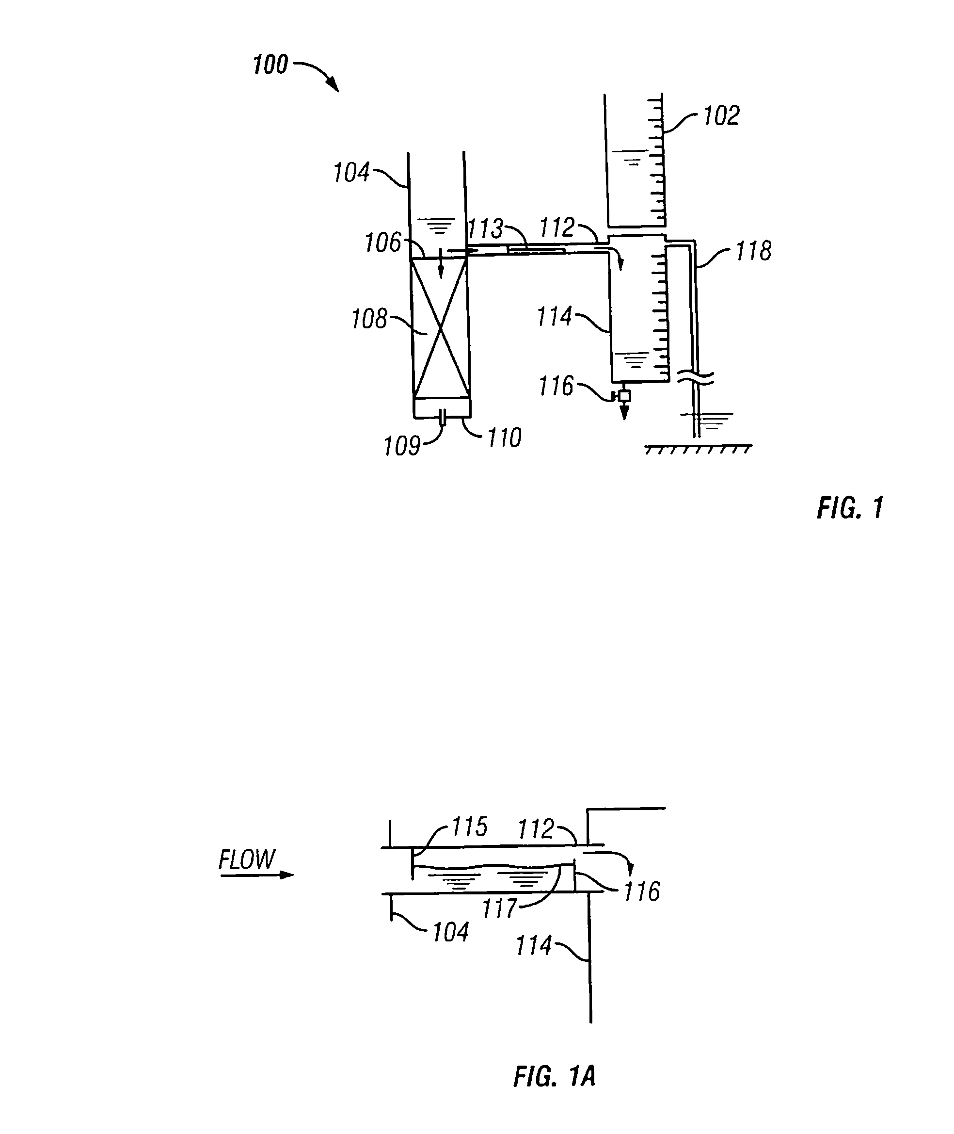
[0042]FIG. 1 illustrates one principal embodiment of the rainfall measuring instrument 100. The device consists of standard rain gauge 102, preferably including graduated markings for determination of rainfall amounts. The instrument 100 also includes a collector tube 104, which includes a flow resistance device 106. The flow resistance device 106 simulates soil infiltration resistance and is preferably comprised of a flow resistance medium 108. Preferably, the flow resistance medium 108 is comprised of a soil sample taken from the site being modeled, of sufficient depth to approximate the natural percolation rate of the soil. This approach allows the resistance to exhibit natural sensitivity to such factors as recent rains or extended dry periods. The soil plug is typically ext...


PUM


Abstract

Disclosed is a runoff rain gauge 100 which includes a collector tube 104, soil infiltration resistance medium 108, a runoff resistance flow element 113, a standard rain gauge 102, and runoff collection tube 114. Precipitation enters the collector tube 104 and is divided to flow into the infiltration medium 108 and runoff collection tube 114 via flow element 113. Total precipitation is read in standard rain gauge 102, runoff in tube 114, and soil infiltration in medium 108 is calculated by the difference between total precipitation and the runoff. Also disclosed are a runoff rain gauge 100 comprising: a seal leg 150 downstream from the runoff resistance flow element 113; a collector tube 104 mounted directly to the ground so that the bottom of the soil infiltration resistance medium 108 contacts the ground surface; and/or a horizontal capillary tube in the runoff resistance flow element 113 to insure self-sealing via capillary forces.

Description

CROSS REFERENCE TO RELATED APPLICATIONS [0001] This application is a continuation-in-part of application U.S. Ser. No. 10 / 709,155, filed Apr. 16, 2004, now U.S. Pat. No. ______, which claims the benefit of provisional application U.S. Ser. No. 60 / 320,123, filed Apr. 18, 2003.BACKGROUND OF INVENTION [0002] This invention relates to a device for capturing rainfall in both a standard rain gauge and a collector tube incorporating an outflow circuit for simulating runoff. The invention provides an estimate of the rainfall split between soil infiltration and runoff. In addition to measuring the total rainfall, the device estimates the amount of runoff, thereby providing an estimate of the soil infiltration by difference. [0003] Prior art rain gauges measure the total amount of precipitation. This can be helpful to serve as a general indicator of how much total rain has fallen, as well as how often and how much irrigation must be provided for crops, for example. However, the prior art rain...

Claims


Application Information

Patent Timeline
IPC IPC(8): G01W1/00
CPCG01W1/14
Inventor NOE, STEPHEN A.
Owner NOE STEPHEN A
Why Eureka
Try Eureka