Cushion for crash attenuation system

a technology of attenuation system and cushion, which is applied in the direction of shock absorbers, elastic dampers, ways, etc., can solve the problems of vehicle movement and dissipation of impacting energy

Inactive Publication Date: 2006-08-31
TMA ACQUISITION
View PDF17 Cites 2 Cited by
  • Summary
  • Abstract
  • Description
  • Claims
  • Application Information

AI Technical Summary

Benefits of technology

[0005] A crash cushion in accordance with one embodiment of the invention has a back plate and an energy absorbing body. The energy absorbing body has two or more sections having cartridges of differing impact absorption. Each of the cartridges is preferably made of a modular, cellular, fibrous, crushable material, such as layers of hexagonal cells of remanufactured fibrous material. The cartridges are encased in water-impermeable bags. The body has a water-impermeable skin of rigid panels sealed together with a suitable tape, such as butyl tape, caulked on the outside, and painted. The panels may be of aluminum, and riveted together. In one embodiment, the body may have two sections joined to one another with a hinge for storage and transportation. In another embodiment, the body may have a proximal section and a distal section, both sealed, and adapted to be joined together along a seam.
[0006] In one embodiment of the invention, a cushion for a crash attenuation system has an energy absorbing body having a proximal end and a distal end. The body includes at least one vertical, longitudinal panel dividing the body into at least two chambers; and cartridges contained in each of the chambers, each of the cartridges having a first and a second transverse face. The cartridges abut each other along their transverse faces and divide the body into sections of differing impact resistance capacities. Each cartridge is made of polygonal cells oriented with their long axes in the long...

Problems solved by technology

Instead, errant vehicles strike the attenuator which arrest...

Method used


Image

  • Cushion for crash attenuation system
  • Cushion for crash attenuation system
  • Cushion for crash attenuation system

Examples


embodiment 700

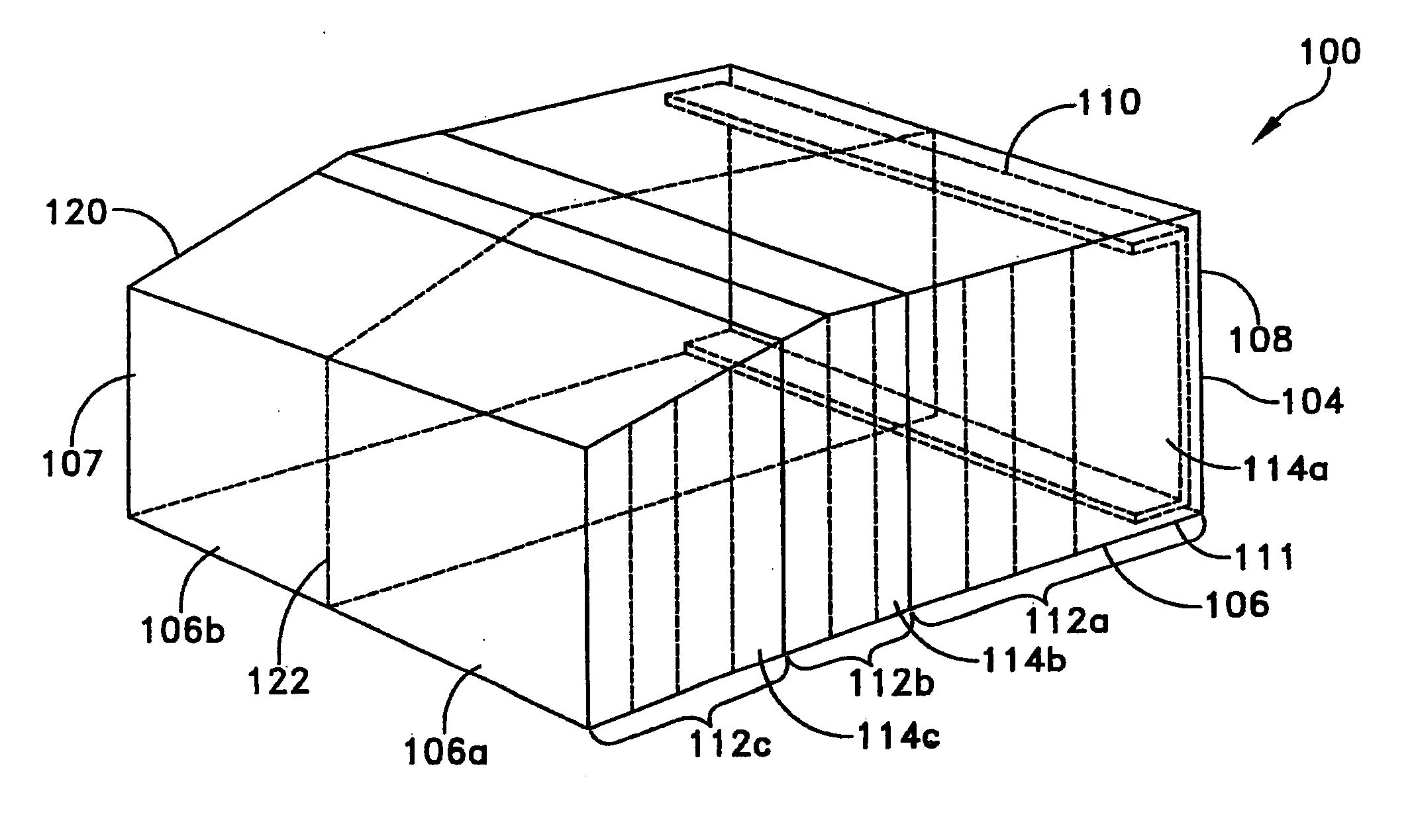
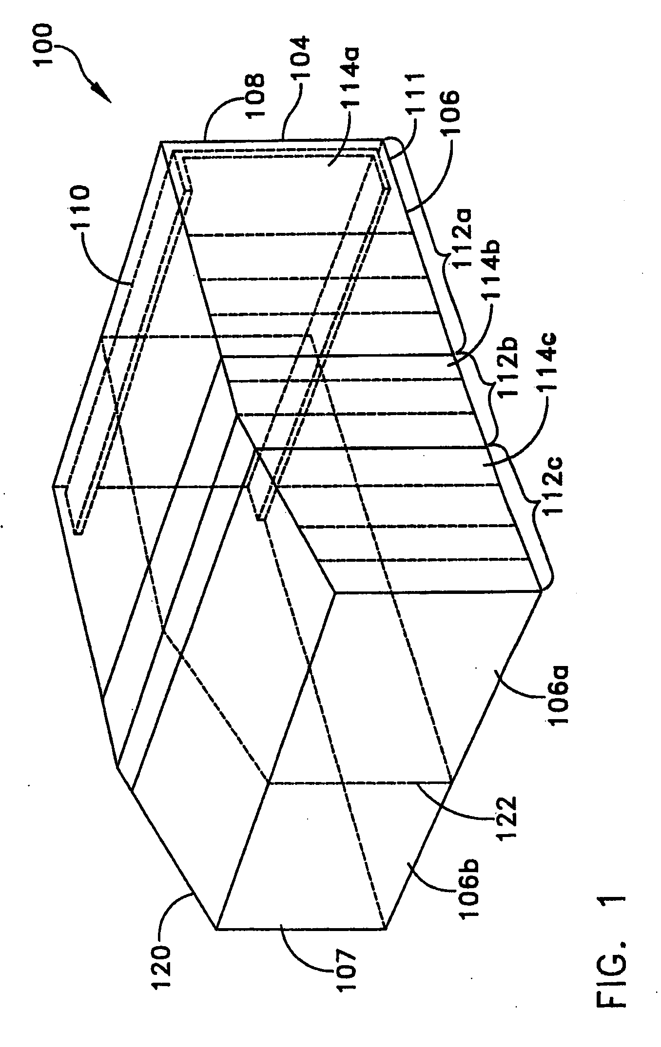
[0073] Referring now to FIG. 7, an embodiment 700 of the cushion of the invention is shown which differs from the embodiment of FIG. 6 only in the overall dimensions and the locations of the interior panels. The internal sections may have different dimensions, but otherwise are identical to those of FIG. 6, and thus are not illustrated. Body 706 has proximal chambers 706a, 706b defined by vertical, longitudinal, generally planar panel 722, indicated in dashed lines in FIG. 7. Panel 722 extends to vertical, transverse, generally planar panel 723, indicated in dashed lines in FIG. 7. Chambers 706c, 706d, 706e, of generally equal dimensions, are defined by panel 723, a second vertical, transverse, generally planar panel 724, and vertical, planar, longitudinal panels 725, 726. It will be appreciated that panel 724, or panels 725, 726, may be made of multiple parts or suitably cut to engage at their respective intersections. Chambers 706f, 706g, 706h, of equal dimensions, are defined by ...

embodiment 1000

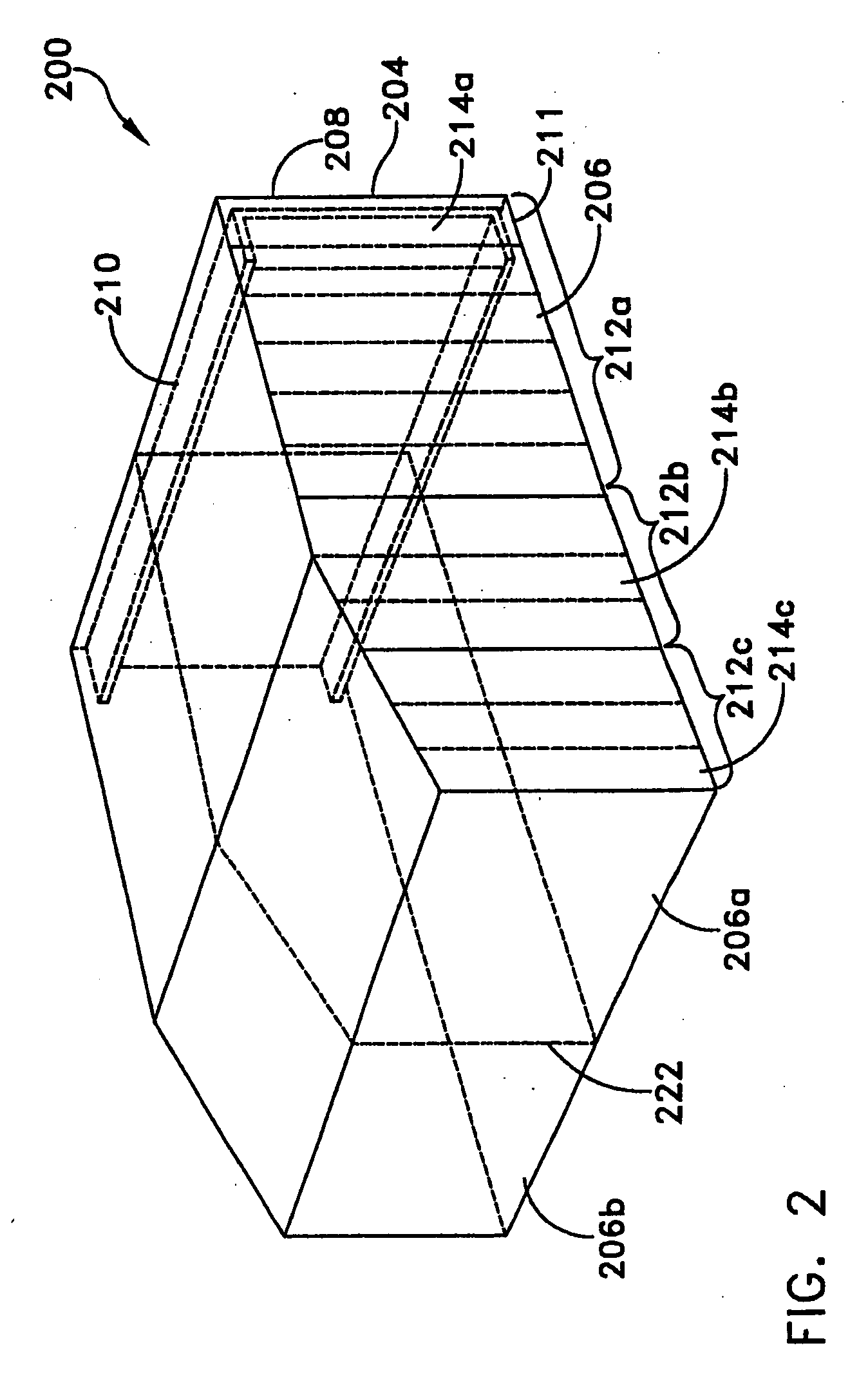
[0081] Referring to FIG. 10, an embodiment 1000 of the cushion of the invention is shown which differs from the embodiment of FIG. 6 only in the overall dimensions, and the locations of the interior panels. The internal sections may have different dimensions, but otherwise are identical to those of FIG. 6, and thus are not illustrated.

[0082] Body 1006 has proximal chambers 1006a, 1006b defined by vertical, longitudinal, generally planar panel 1022, indicated in dashed lines in FIG. 10. Panel 1022 extends to vertical, transverse, generally planar panel 1023, indicated in dashed lines in FIG. 10. Chambers 1006c, 1006d, 1006e, of generally equal dimensions, are defined by panel 1023, a second vertical, transverse, generally planar panel 1024, and vertical, planar, longitudinal panels 1025, 1026. It will be appreciated that panel 1024, or panels 1025, 1026, may be made of multiple parts or suitably cut to engage at their respective intersections. Chambers 1006f, 1006g, 1006h, of equal d...


PUM


Abstract

A crash cushion in accordance with the invention has a back plate and an energy absorbing body. The energy absorbing body has three or more sections having cartridges of differing impact absorption. Each of the cartridges is preferably made of layers of hexagonal remanufactured fibrous material cells. The cartridges are encased in water-impermeable bags. The body has a water-impermeable skin of rigid panels sealed together with a suitable tape, such as butyl tape, caulked on the outside, and painted. The panels may be of aluminum, and riveted together. In one embodiment, the body may have two sections, both with a water-impermeable skin, joined to one another with a hinge for storage and transportation. In another embodiment, the body may have a proximal section and a distal section, both sealed, and adapted to be joined together along a seam. The distal section can be removed and replaced separately from the proximal section, such as if only the distal section is damaged by a relatively low-speed impact.

Description

RELATED APPLICATIONS [0001] This application claims the benefit of U.S. Provisional Patent Application Ser. No. 60 / 656,268, filed Feb. 25, 2005, which is hereby incorporated by reference herein in its entirety.FIELD OF THE INVENTION [0002] The present invention relates to vehicle-mounted crash attenuation systems. BACKGROUND OF THE INVENTION [0003] Crash attenuation devices have been developed for mounting on vehicles that are parked or moving slowly on roadways, for example at construction or maintenance sites, in order to attenuate the impacts from collisions with the parked vehicle. Often times, vehicles equipped with crash attenuators are purposely deployed around work sites to shield workers at the site from being hit. Instead, errant vehicles strike the attenuator which arrests the motion of the vehicle and dissipating its impacting energy. Examples of these attenuation devices are disclosed in U.S. Pat. Nos. 6,186,565, 6,098,767, 5,052,732, 4,635,981, and 4,658,941 incorporat...

Claims


Application Information

Patent Timeline
IPC IPC(8): F16F7/12
CPCB60R19/00B60R19/205B60R2019/005E01F15/148F16F7/12
Inventor UNRATH, ALBERT W. SR.
Owner TMA ACQUISITION
Why Eureka
Try Eureka