
Projection type video reproducing apparatus

a video reproducing and projection type technology, applied in the field of projection type video reproducing apparatus, can solve the problems of unstable light emission just after turning on the light source, trouble during video reproduction, and preheating the light source, so as to prolong the life of the light source and maintain the linearity of the light intensity

Inactive Publication Date: 2006-08-31
YAMAHA CORP
View PDF6 Cites 41 Cited by
  • Summary
  • Abstract
  • Description
  • Claims
  • Application Information

AI Technical Summary

Benefits of technology

The invention is a projection type video reproducing apparatus that uses high-speed response devices, such as LEDs, as a light source for applying projection light onto a video display element. The apparatus includes a video display element drive circuit, a video signal conversion portion, and a light source drive circuit. The video signal conversion portion detects peak values of the video signal and calculates a conversion coefficient based on these peak values. The conversion coefficient is used to increase the luminance value of the video signal and reduce the light intensity of the light source. The light intensity control process is performed based on the conversion coefficient to achieve power saving. The invention provides a more efficient and effective way to save power in projection type video displays.

Problems solved by technology

That is, the light source has to be preheated because light emission just after turning-on of the light source is unstable.
A heat radiation fan has to be used because the light source generates a large amount of heat (self-generated heat and radiant heat).
Driving noise of the fan causes trouble during video reproduction.
Even after the light source is turned off, the fan cannot be stopped soon because the light source has to be cooled after use.
There is a problem that efficiency is lowered at the stage where light emitted from the LEDs is condensed.

Method used


Image

  • Projection type video reproducing apparatus
  • Projection type video reproducing apparatus
  • Projection type video reproducing apparatus

Examples


Embodiment Construction

[0047] I. Description of Configuration of Apparatus

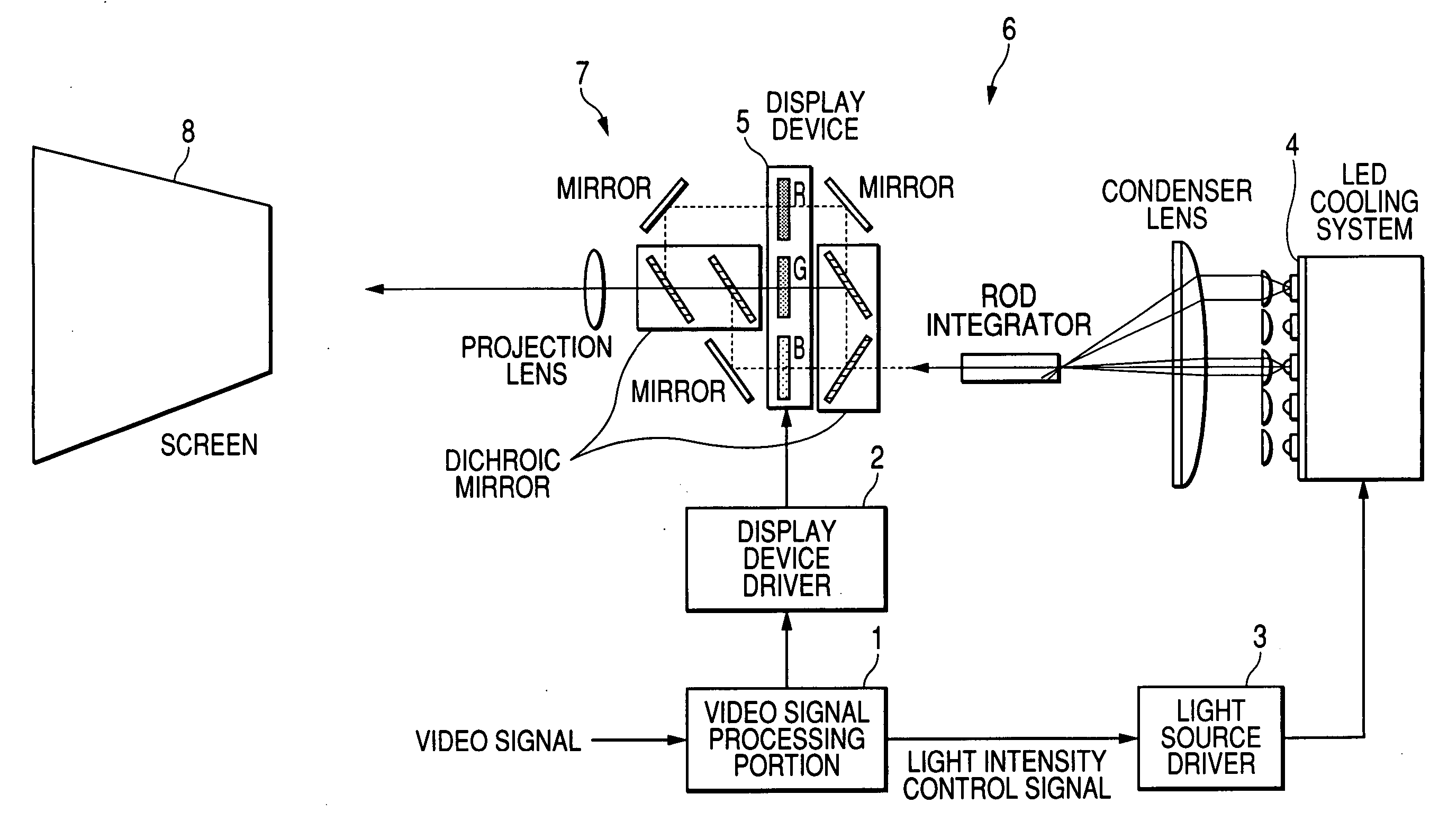
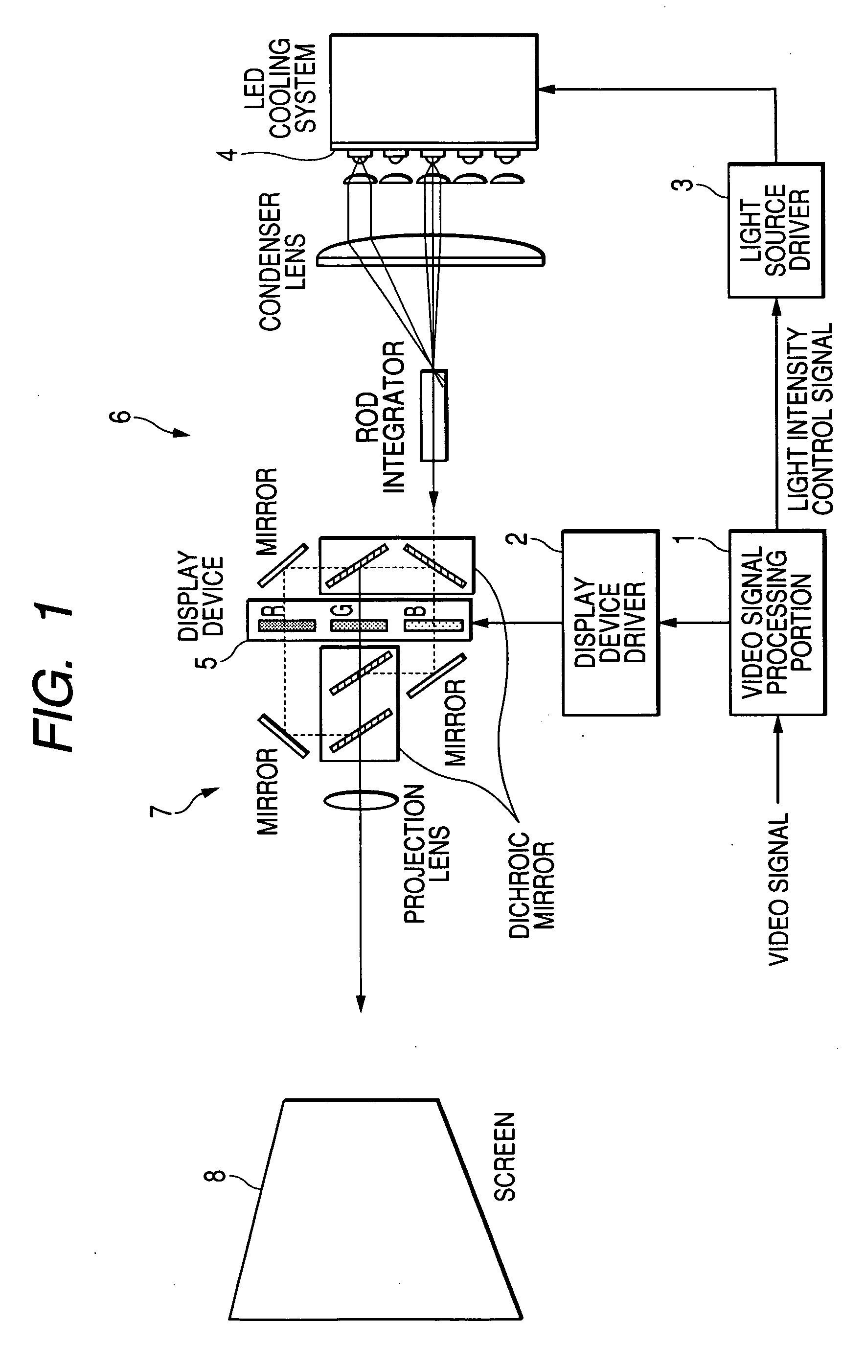
[0048] A projection type video reproducing apparatus (projector) according to an embodiment of the invention will be described with reference to the drawings. The projection type video reproducing apparatus makes a display device such as a digital mirror device display video and makes an LED light source apply light on the video to project the video on a screen.

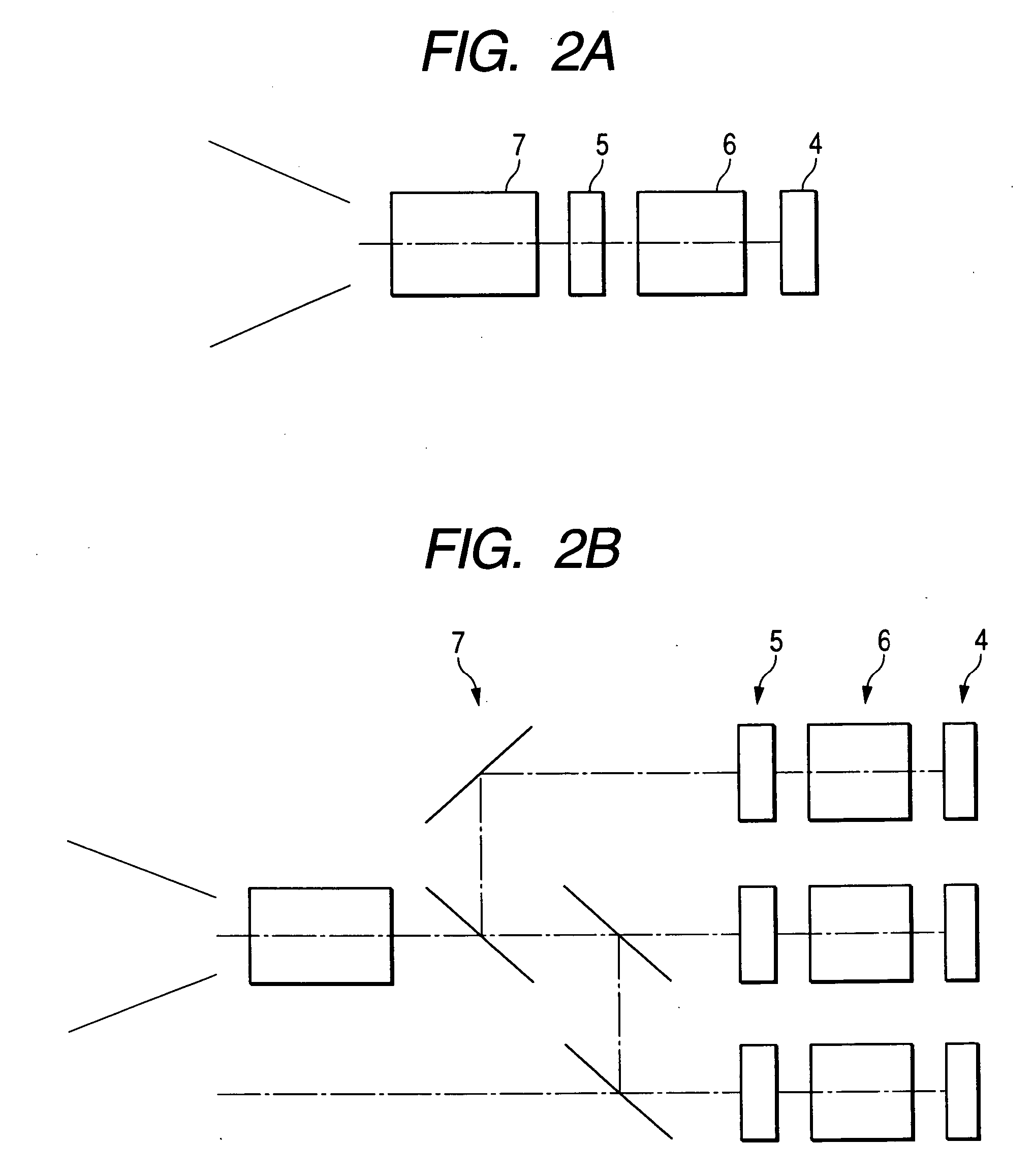
[0049]FIG. 1 is a block diagram of the projection type video reproducing apparatus. The projection type video reproducing apparatus includes: a display device 5 for visualizing a video signal; a light source 4 for applying projection light on the display device 5; a light-condensing optical system 6 for leading light of the light source 4 to the display device 5; and a projection optical system 7 by which video displayed on the display device is projected on the screen. The projection type video reproducing apparatus further includes: a display device driver 2 for driving t...


PUM


Abstract

A projection type video reproducing apparatus includes a video display element that visualizes a video signal, a video display element drive circuit that drives the video display element, a high-speed response light source that applies projection light onto the video display element, a light source drive circuit that turns the light source on, and a video signal conversion portion. The video signal conversion portion executes: a peak detection process for detecting peak values of luminance of the video signal at intervals of a unit time; a conversion coefficient calculation process for calculating a conversion coefficient based on a ratio of each detected peak value to an upper limit of the luminance or based on a difference between each detected peak value and an upper limit of the luminance; a video signal conversion process for converting the luminance value of the video signal in the unit time based on the conversion coefficient so as to increase the luminance value and supplying the luminance value to the video display element drive circuit; and a light intensity control process for setting a control value based on the conversion coefficient to reduce the light intensity of the light source and controlling the light source drive circuit in accordance with the control value.

Description

BACKGROUND OF THE INVENTION [0001] The present invention relates to a projection type video reproducing apparatus for enlarging and projecting video on a screen. [0002] A projector is known as an apparatus for enlarging and reproducing video. The projector is an apparatus provided with an optical system through which video is projected on a screen set up on a wall surface. A back type apparatus has been also put into practice. That is, the back type apparatus is provided with a housing having a front surface on which a screen is provided so that video is projected on the screen from a back surface of the inside of the housing. [0003] A light source such as a mercury lamp or a halogen lamp has been heretofore used in such a projection type video reproducing apparatus because of necessity of strong projection light (e.g. JP-A-2004-264668). [0004] The light source such as a mercury lamp or a halogen lamp, however, has the following drawbacks. That is, the light source has to be preheat...

Claims


Application Information

Patent Timeline
Patent Type & Authority Applications(United States)
IPC IPC(8): H04N9/31
CPCH04N9/3105H04N9/312H04N9/3155H04N9/3197
Inventor OGITA, MINORU
Owner YAMAHA CORP
Learn More