Method and apparatus for trace gas detection

a trace gas and detection method technology, applied in the direction of instruments, measurement devices, color/spectral property measurements, etc., can solve the problems of difficult sensitivity and high precision of trace gas detection in measuring gas, and achieve the effect of improving the accuracy of measurement and significantly improving accuracy

Active Publication Date: 2006-08-31
SIEMENS AG
View PDF12 Cites 26 Cited by
  • Summary
  • Abstract
  • Description
  • Claims
  • Application Information

AI Technical Summary

Benefits of technology

The invention is about a method to measure the level of a trace gas accurately. It does this by measuring the light absorption of a purge gas after purging the optical path from a light source to a measuring volume and then to a measuring detector. This allows for real-time compensation of any offset in the measured gas level caused by impurities in the purge gas. The method also adjusts the measured light absorptions of the measuring gas and the purge gas using a scaling factor that takes into account the ratio of the purged optical path length and the purged length of the second optical path. This improves the accuracy of the measurement and makes it applicable even when the pressure and absorption line broadening in the measuring gas and the purge gas are different.

Problems solved by technology

The technical problem addressed in this patent text is the difficulty in accurately detecting trace gases in a gas mixture, particularly when the main ingredient of the gas mixture absorbs light at the same wavelengths as the trace gas and in greater amounts. The text describes various methods for eliminating interfering absorption, including the use of a cancel gas and the removal of atmospheric gases using a reference cell. The text also discusses the issue of moisture contamination in the gas sample and proposes methods for preventing it, such as using a purge gas or flushing the optical paths.

Method used


Image

  • Method and apparatus for trace gas detection
  • Method and apparatus for trace gas detection

Examples


Embodiment Construction

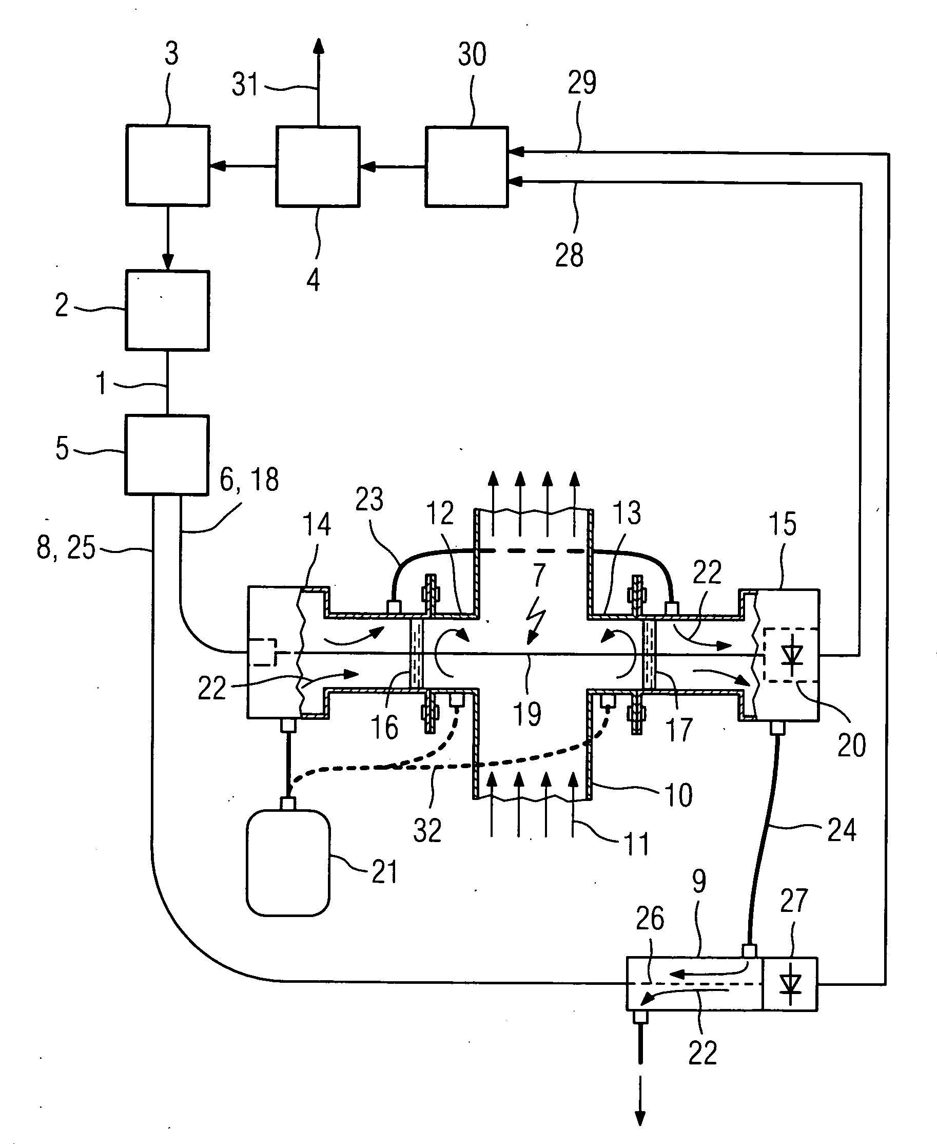
[0016] Light 1 having a suitable wavelength for spectroscopic gas analysis is emitted from a light source 2, here a tunable diode laser, which is driven by a laser controller 3. The laser controller 3 controls the injection current and / or the temperature of the diode laser 2 according to information provided by a computer 4 so as to continuously vary the wavelength of the emitted light 1 over a desired wavelength range for analysis. The light 1 is split by means of an optical coupler 5 into a first portion 6 for passing through a measuring volume 7 and a second portion 8 for passing through a compensation volume 9.

[0017] In the shown example the measuring volume 7 is part of a gas pipe 10 through which a process gas, the measuring gas 11, flows. The measuring gas 11 may be chlorine, the moisture content of which has to be determined. Two flange tubes 12 and 13 are welded at diametrically opposed positions into the wall of the gas pipe 10. A transmitter unit 14 and a receiver unit 1...


PUM


Abstract

In spectroscopic devices the sections of an optical measuring path from a light source to a measuring volume containing a measuring gas and from there to a measuring detector are often sealed off from the ambient atmosphere and purged with a purge gas such as dry nitrogen to prevent penetration of atmospheric gas components, such as water vapor, which may interfere with the trace gas measurement. The moisture content in the nitrogen supply is usually in the range of a few ppm at the gas source and can increase dramatically at the measuring site depending on the length of the nitrogen pipe net and due to porosity of the pipe walls, leakage of seals and residual moisture trapped in so-called dead legs. In order to compensate interfering absorption of atmospheric gas components and other impurities in the purge gas the purge gas is collected after flushing the optical path sections, a portion of the light of the light source is transmitted along a second optical path to a compensation detector, the second optical path is flushed with the collected purge gas and the trace gas component in the measuring gas is determined based on a difference between the output of the measuring detector and the output of the compensation detector.

Description


Claims


Application Information

Patent Timeline
Owner SIEMENS AG
Why Eureka
Try Eureka