Multiple output illumination using reflectors

Active Publication Date: 2006-08-31
MEADOWSTAR ENTERPRISES
View PDF4 Cites 4 Cited by
  • Summary
  • Abstract
  • Description
  • Claims
  • Application Information

AI Technical Summary

Problems solved by technology

Light striking the interface between the core and the cladding at an angle of incidence greater than a so-called critical angle, on the other hand, may not be maintained within the optical fiber core.
If the fiber is too long, the intensity may drop eventually to a point such that the uniformity will not be acceptable, but where illumination is desired.
If the fiber is too short, too much light will make it to the other end without providing illumination, and thus will be wasted.
Packing two circular fibers together side-by-side, however, may be inefficient since the output of an illuminator will generally be circular as well, and a circular light pattern shown on two adjacent circular input ends will result in losses between the input ends.

Method used


Image

  • Multiple output illumination using reflectors
  • Multiple output illumination using reflectors
  • Multiple output illumination using reflectors

Examples


first embodiment

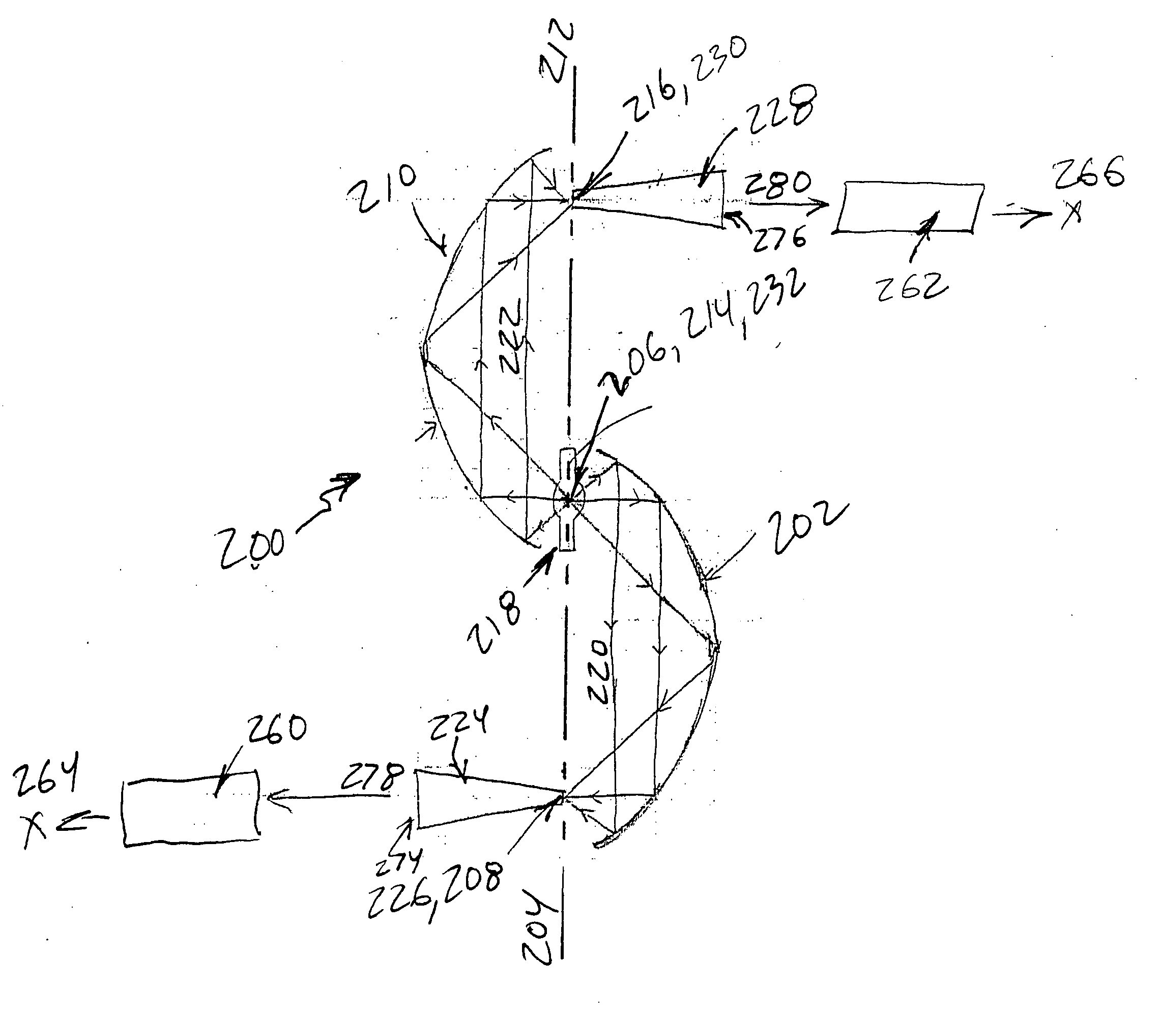
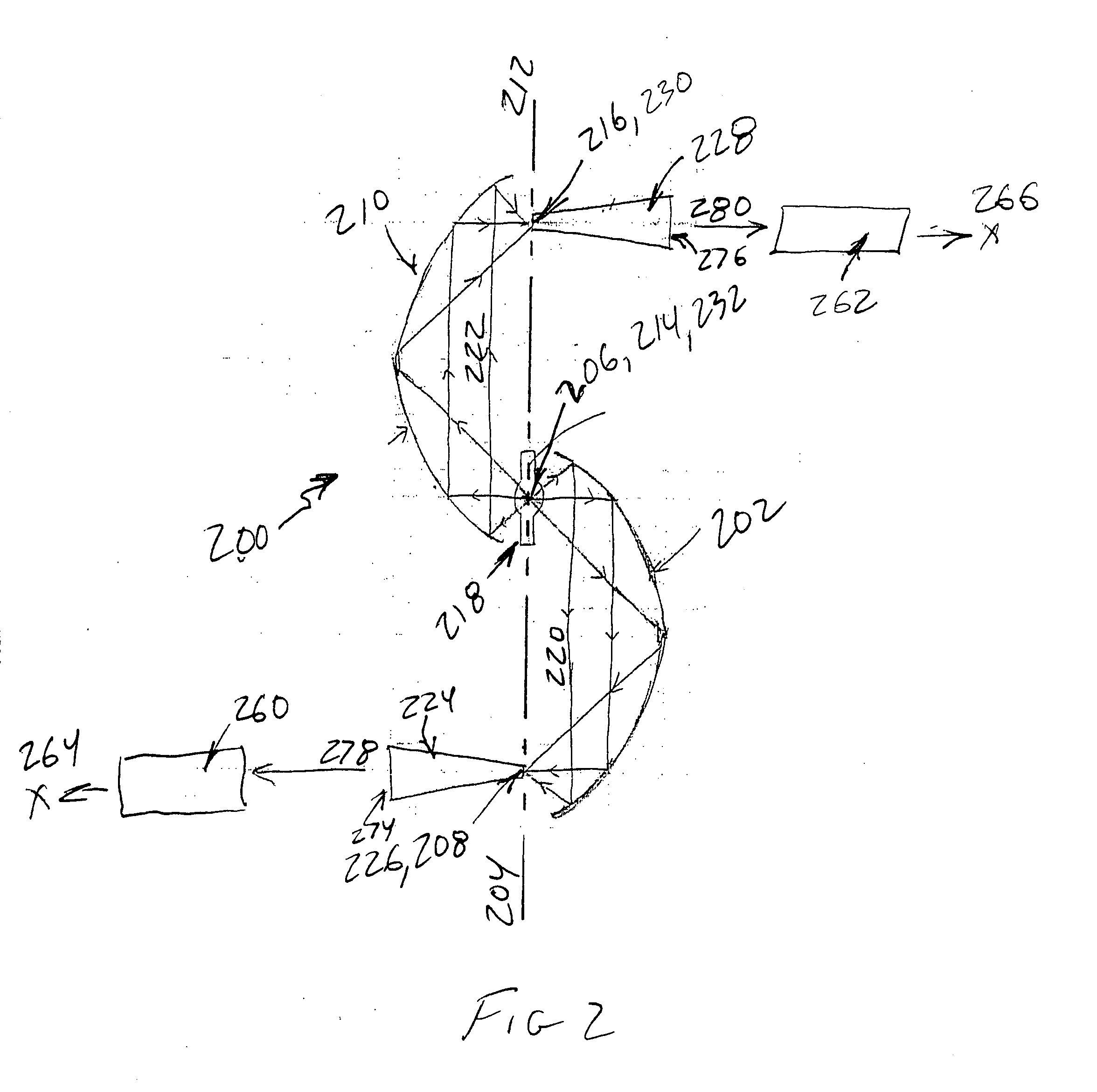
[0029] In FIG. 2 is shown a multiple output illumination system 200 according to the invention. Multiple output illumination system 200 may include first and second reflectors 202, 210. In one embodiment, first and second reflectors 202, 210 may have a coating that reflects only a pre-specified portion of electromagnetic radiation spectrum, such as visible light radiation, a pre-specified band of radiation, or a specific color of radiation.

[0030] First reflector 202 may have a first optical axis 204 and a first and second focal points 206, 208. First and second focal points 206, 208 may be substantially on first optical axis 204. Second reflector 210 may have a second optical axis 212 and a third and fourth focal points 214, 216. Third and fourth focal points 214, 216 may be substantially on second optical axis 212. Third focal point 214 may be substantially proximate to first focal point 206 while fourth focal point 216 may be substantially distal from second focal point 208. In va...

second embodiment

[0043] In FIG. 3 is shown a multiple output illumination system 300 according to the invention. Illumination system 300 includes a first, second and third reflectors 302, 310, 334 arranged substantially rotationally symmetrically about an axis of rotation 332. In one embodiment, first, second and third reflectors 302, 310, 334 may be approximately 120° from one another around axis of rotation 332.

[0044] First reflector 302 may have a first optical axis 304 and a first and second focal points 306, 308. First and second focal points 306, 308 may be substantially on first optical axis 304.

[0045] Second reflector 310 may have a second optical axis 312 and a third and fourth focal points 314, 316. Third and fourth focal points 314, 316 may be substantially on second optical axis 312. Third focal point 314 may be substantially proximate to first focal point 306 while fourth focal point 316 may be substantially distal from second focal point 308.

[0046] Third reflector 334 may have a thir...

eighth embodiment

[0069] In an eighth embodiment, a method for collecting electromagnetic radiation emitted by a source 618 of electromagnetic radiation and substantially focusing collected radiation onto a plurality of targets includes positioning source 618 of electromagnetic radiation substantially at a focal point 606, 614 of a first and second reflectors 602, 610, producing first and second rays of radiation 622 by source 618, reflecting first rays of radiation 620 by first reflector 602 substantially toward a third reflector 634 and reflecting second rays of radiation 622 by second reflector 610 substantially toward a fourth reflector 642, converging first rays of radiation 620 substantially at a focal point 608 of third reflector 634 and converging second rays of radiation 622 substantially at a focal point 616 of fourth reflector 642, positioning a first light pipe 624 may have a first input end 626 and a first output end 674 so that first input end 626 is substantially proximate to focal poi...


PUM


Abstract

A multiple output illumination system includes a first and second reflectors each having an optical axis and a first and second focal points substantially on the optical axis. In one embodiment, one of the focal points of each reflector are proximate to one another, while the other focal point of each reflector is distal from each other. In another embodiment, the first and second reflectors are pairs of reflectors, and the second reflector of each points away from the optical axes of the first and second reflectors. An intermediate reflector may redirect radiation from the second reflectors. A source of electromagnetic radiation substantially proximate to the focal points that are proximate to one another produces rays of radiation that are reflected by the each reflector in different directions, converging substantially at each of the distal focal points. Light pipes placed substantially proximate to the distal focal points may collect the radiation.

Description

CROSS-REFERENCE TO RELATED APPLICATIONS [0001] This application claims benefit of Provisional Application Ser. Nos. 60 / 415,753, filed Oct. 4, 2002, and 60 / 418,169, filed Oct. 15, 2002, the disclosures of which are incorporated by reference.FIELD OF THE INVENTION [0002] The invention relates to illuminators for coupling light into light guides such as optical fibers. DESCRIPTION OF THE RELATED ART [0003] Optical fibers may be used to transport light. Optical fibers are often designed to maximize the portion of the light launched into the fiber that exits at the end of the fiber. Side-lit optical fibers, on the other hand, are constructed so that the cladding allows a portion of the light traveling through the core of the fiber to exit from the sides of the fiber, rather than being retained until it reaches the end of the fiber. Side-lit optical fibers thus essentially ‘leak’ light. The leaked light appears to be illumination to one viewing the optical fiber from the side, hence the t...

Claims


Application Information

Patent Timeline
IPC IPC(8): F21V7/04F21VF21V7/00F21V7/06F21V7/07F21V7/08
CPCF21V7/0025F21V7/06G02B17/06F21V7/08G02B6/4298F21V7/07
Inventor LI, KENNETHKSILLYMAN, SHELDON
Owner MEADOWSTAR ENTERPRISES
Why Eureka
Try Eureka