
Foundation headboard bracket system for bed

Active Publication Date: 2006-09-07
FINGER LAKES INTPROP
View PDF15 Cites 15 Cited by
  • Summary
  • Abstract
  • Description
  • Claims
  • Application Information

AI Technical Summary

Benefits of technology

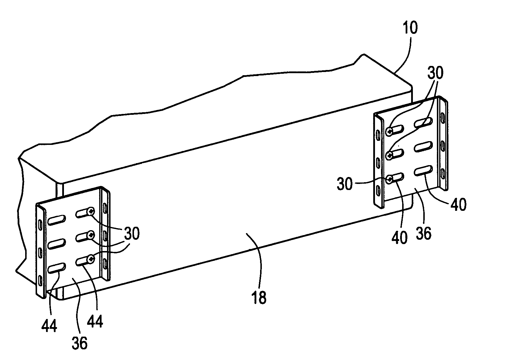
[0011] As such, in order to affix the headboard to the bed foundation, the foundation bracket and the slide bracket are affixed together and that affixation is accomplished by nesting one of the brackets into the other. In the embodiment described, the lateral side plates of the slide bracket fit adjacent to and outwardly of the lateral side plates of the foundation bracket. When so nested, securing devices, such as carriage or other bolts, pass laterally between both brackets in order to secure those brackets together. With two sets of brackets, that is, a foundation bracket and a slide bracket located at opposed ends of the head end of the bed foundation, the eventual affixing of the headboard to the bed foundation results in a solid connection that can be carried out relatively easily.

Problems solved by technology

There are certain difficulties, however, in the simple attachment of the headboard to a bed foundation through the use of the flat, adjustment bracket.
One of the difficulties lies in the basic construction of the typical adjustment bracket itself which is a relatively weak, flat stamped metal construction and is simply not strong enough to carry out the task of affixing the bed foundation to the headboard, particular where many of the bed foundations are sold with more expensive, heavy, decorative headboards creating consider leverage and joint strain on the adjustment bracket and causing a premature failure of the connection between the bed foundation and the headboard.
In addition there is a difficulty in carrying out the connection between the adjustment bracket and the headboard in that the adjustment bracket is affixed directly to the bed foundation and there is, therefore, very limited access to the side of the adjustment bracket that faces the bed foundation.
As such, with a bed foundation type of bed, it is generally quite difficult and cumbersome to thread a bolt through the adjustment bracket and through the headboard holes due to the rather limited space in which to thread the bolts through the adjustment bracket.

Method used


Image

  • Foundation headboard bracket system for bed
  • Foundation headboard bracket system for bed
  • Foundation headboard bracket system for bed

Examples


Embodiment Construction

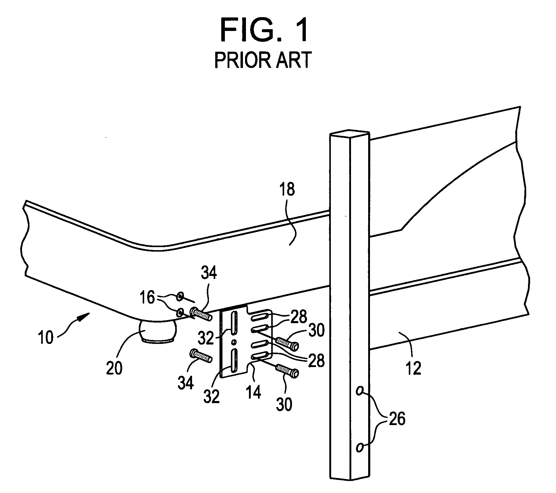
[0025] Referring now to FIG. 1, there is shown an exploded view of a conventional bed foundation 10 in position to be affixed to a headboard 12. As can be seen, there is also an adjustment bracket 14 that is positioned intermediate the bed foundation 10 and the headboard 12 and which is used to complete the affixation of the bed foundation 10 to the headboard 12. There is a pair of threaded inserts 16 shown in FIG. 1 that are vertically spaced apart and a similar pair of threaded inserts are located (not shown) at the opposite side of the head end 18 of the bed foundation 10 and the location and type of threaded inserts 16 are conventional on bed foundations.

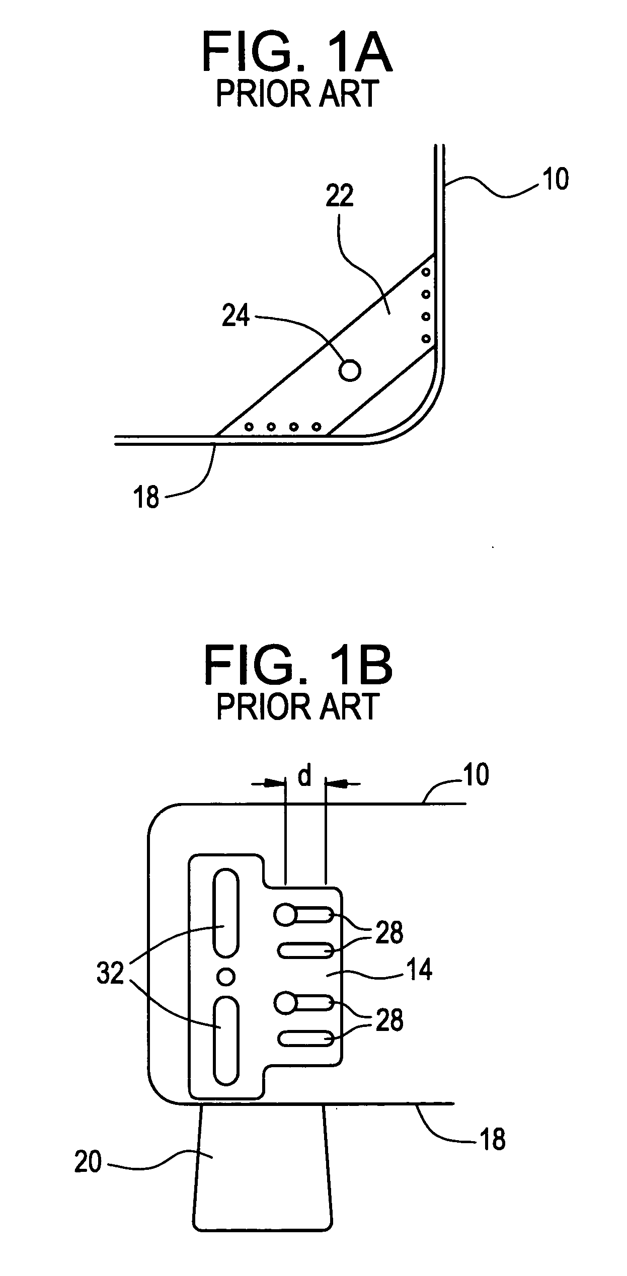
[0026] The bed foundation 10 also has a leg 20 extending downwardly from the bed foundation 10 in order to maintain the bed foundation 10 above the floor and there are generally four legs, one at each corner of the generally rectangular bed foundation 10. Turning briefly to FIG. 1A, taken along with FIG. 1, there is a bottom vi...


PUM


Abstract

A bracket system for attaching a headboard to a bed foundation. The bracket system includes a foundation bracket affixed to the bed foundation and a slide bracket affixed to the headboard. Each of the brackets is generally U-shaped having a pair of side plates extending outwardly therefrom. The dimensions and spacing of the side plates enables one bracket to interfit or nest within the other bracket. A securing device passes through both the foundation bracket and the slide bracket to secure the brackets together and affix the headboard to the bed foundation. In an alternate embodiment, the foundation brackets have a lower plate and side plates extending upwardly therefrom and are affixed to the head comers of the bed foundation. The slide bracket is affixed to the headboard and then to the directly to the bed foundation through the foundation bracket. In a further embodiment, the foundation bracket is eliminated.

Description

REFERENCE TO RELATED APPLICATIONS [0001] The present patent application is based upon and hereby claims priority to Provisional patent application Ser. No. 60 / 652,987, filed Feb. 15, 2005.BACKGROUND OF THE INVENTION [0002] The present invention relates to a means of attaching a bed foundation to a headboard in the assembly of a bed and, more particularly, to a foundation headboard bracket system that provides a versatile, bracket system for firmly affixing a bed foundation to a headboard. [0003] In general, there are a number of differing types of bed frames and constructions used in the assembly and formation of a bed. One typical construction is with the use of a bed frame where there are side rails having cross members that are pivotally affixed at or proximate to the ends of the side rails. During shipment, for convenience, the cross members are in a position parallel to and adjacent to the side rails and, during the assembly of the bed frame, those cross members are pivoted out...

Claims


Application Information

Patent Timeline
IPC IPC(8): A47C19/02
CPCA47C19/021A47C19/022F16B12/56
Inventor POLEVOY, RICHARD S.CARLSON, PAUL ERIC
Owner FINGER LAKES INTPROP
Learn More