electronic circuit device

A technology of electronic circuits and circuit boards, which is applied in the direction of circuits, printed circuits, printed circuits, etc., can solve the problems of high frame cost and less versatility, and achieve the effect of simple assembly

Active Publication Date: 2020-05-19
海拉有限双合股份公司
View PDF8 Cites 0 Cited by
  • Summary
  • Abstract
  • Description
  • Claims
  • Application Information

AI Technical Summary

Problems solved by technology

These frameworks are relatively expensive and rarely universal

Method used


Image

  • electronic circuit device
  • electronic circuit device
  • electronic circuit device

Examples


Embodiment Construction

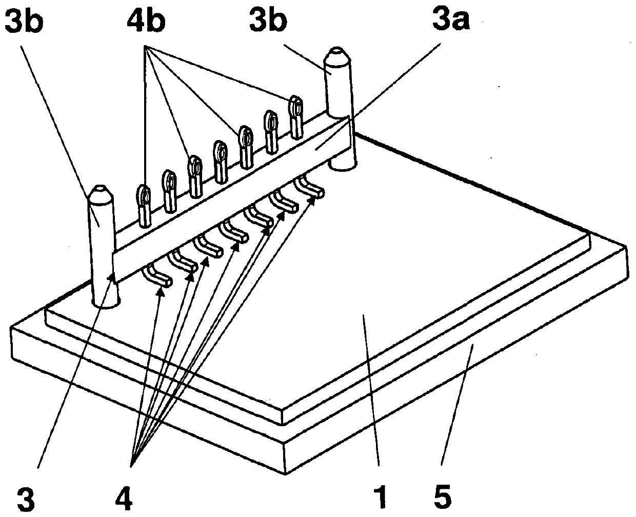
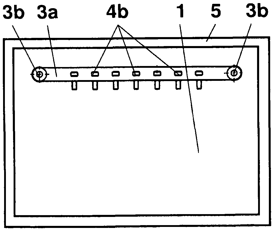
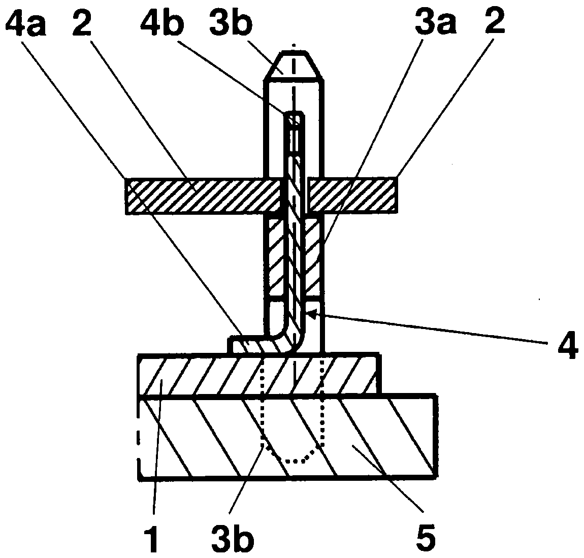
[0018] As from according to one embodiment Figures 1 to 3 As seen in , a circuit arrangement includes two circuit boards 1 , 2 and a connector 3 .

[0019] The circuit boards 1, 2 are equipped with electrical and / or electronic components (only in Figure 4 partly shown in ) and are positioned relative to each other, that is to say aligned relative to each other. These circuit boards are arranged substantially parallel to each other or at an acute angle. The components are attached to the printed circuit boards 1 , 2 in the generally known SMD technology (SMD=surface mounted device). Furthermore, the printed circuit boards 1 , 2 are in contact with one another.

[0020] The connector 3 is designed substantially as an elongated cross-beam 3 a with a rectangular cross-section and with laterally formed supports 3 b. The length of the crossbeam 3 a is dimensioned according to the number of contacting elements 4 in such a way that on the one hand the contacting elements have a ...


PUM


Abstract

The invention concerns an electronic circuit, comprising a first printed circuit board (1) with electronic components and a second printed circuit board (2) with electronic components, the printed circuit boards (1, 2) being disposed parallel to their main faces or at an acute angle adjacent or one above the other . The circuit is intended to be produced more simply and economically. This is achieved in that the printed circuit boards (1, 2) are held, positioned and electrically connected by means of a beam-shaped connector (3).

Description

technical field [0001] The invention relates to an electronic circuit arrangement comprising a first circuit board with electronic components and a second circuit board with electronic components, wherein the circuit boards are arranged parallel to their main faces or at an acute angle alongside or overlap each other set up. Background technique [0002] Such circuit arrangements are known per se. They can include intelligent circuitry and / or controllers and are used, for example, for electric drives. Especially in the construction of motor vehicles, the tight space must be taken into account, so that the drive including the circuit arrangement must be constructed very compactly in the case of relatively high power. This means that the required electrical and / or electronic components of the circuit arrangement cannot be arranged on a single circuit board, but must be distributed over a plurality of smaller circuit boards. These small printed circuit boards must be at leas...

Claims


Application Information

Patent Timeline
Patent Type & Authority Patents(China)
IPC IPC(8): H01R12/52H01R12/55
CPCH05K1/144H05K3/368H05K2201/042H05K2201/10318H05K2201/10424H05K2203/167
Inventor M·波扎O·维兰
Owner 海拉有限双合股份公司
Why Eureka
Try Eureka