Expansion valve

Inactive Publication Date: 2006-09-07
TGK
View PDF4 Cites 16 Cited by
  • Summary
  • Abstract
  • Description
  • Claims
  • Application Information

AI Technical Summary

Benefits of technology

[0014] The present invention has been made in view of the problems, and an object thereof is to enhance the manufacturing eff

Problems solved by technology

However, the cutting process takes a long machining time period and is low in yield, resulting in increased manufacturing costs of the expansion valve.
This makes it impossible to apply the extrusion to the formation of the first passage with which a valve seat as a component part of a valve section is integrally formed in an intermediate portion thereof.
Further, although at ends of the first and second passages, there are formed sealing surfaces of sealing members which are interposed for connection of pipes connected to the compressor, the receiver, and the evaporator, the sealing surfaces cannot be formed by extrusion molding, since the end portions are diametrically expanded.
Therefore, as for these portions, there is still no other way but employ machining by cutting, which makes it impossible to sufficiently reduce the amount of used materials and enhance manufacturing efficiency.
Further, when the second passage is formed by the hollow extrusion, and then the ends thereof are to be cut by a lathe, for example, it is not easy to cause the axis of the passage during extrusion molding and the axis of the rotating shaft during a cutting process to coinci

Method used


Image

  • Expansion valve
  • Expansion valve
  • Expansion valve

Examples


Example

First Embodiment

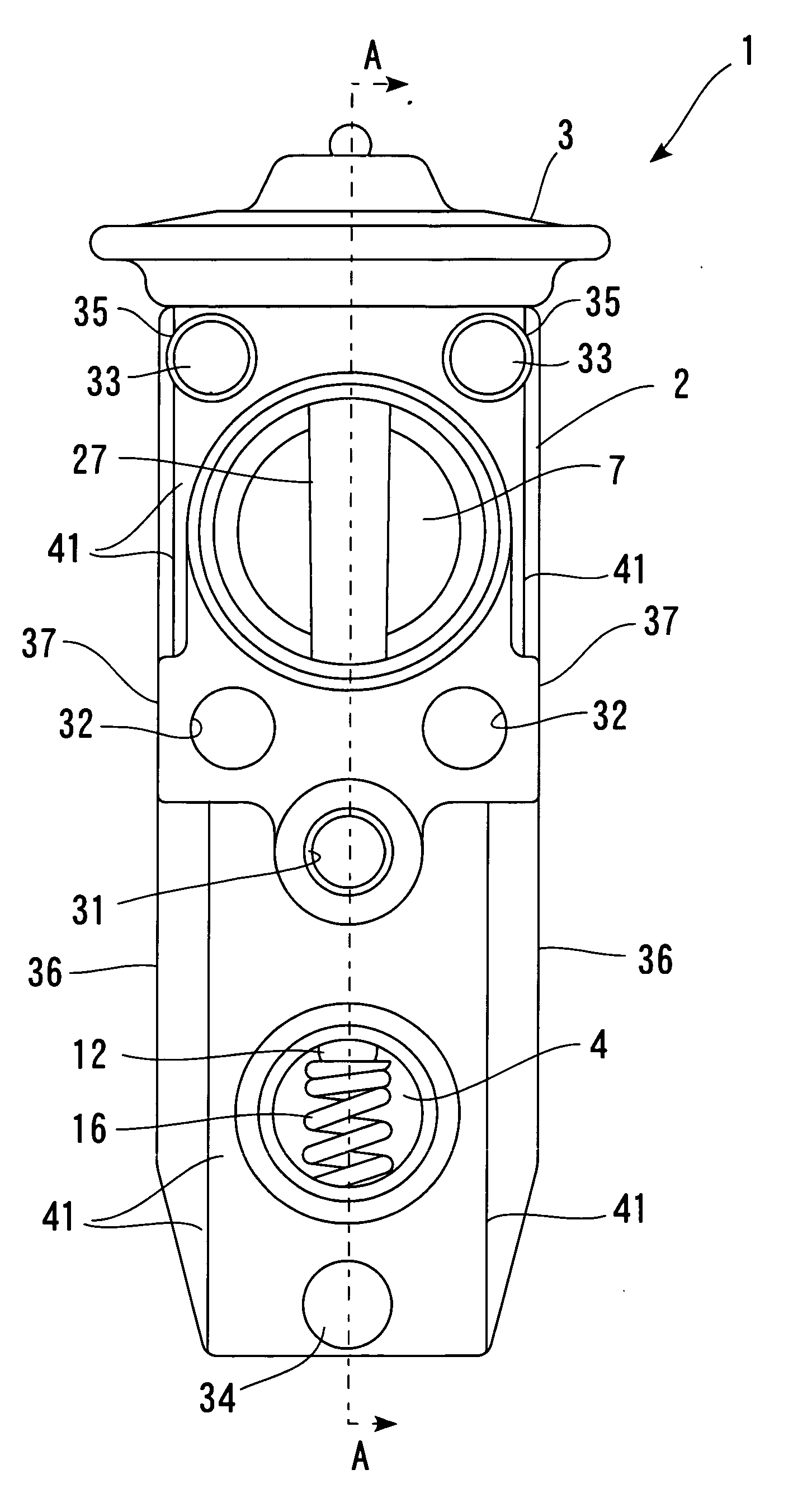
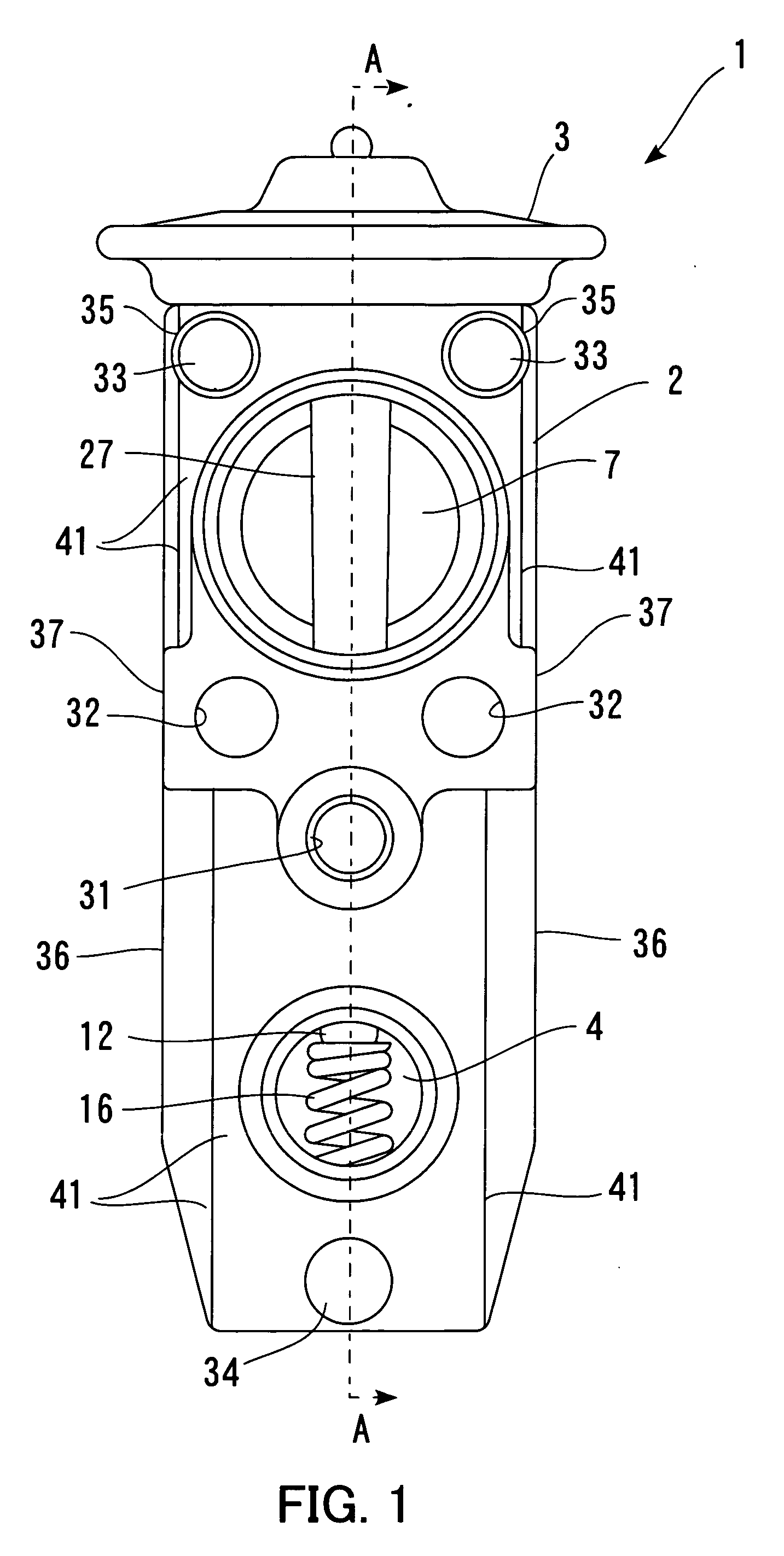
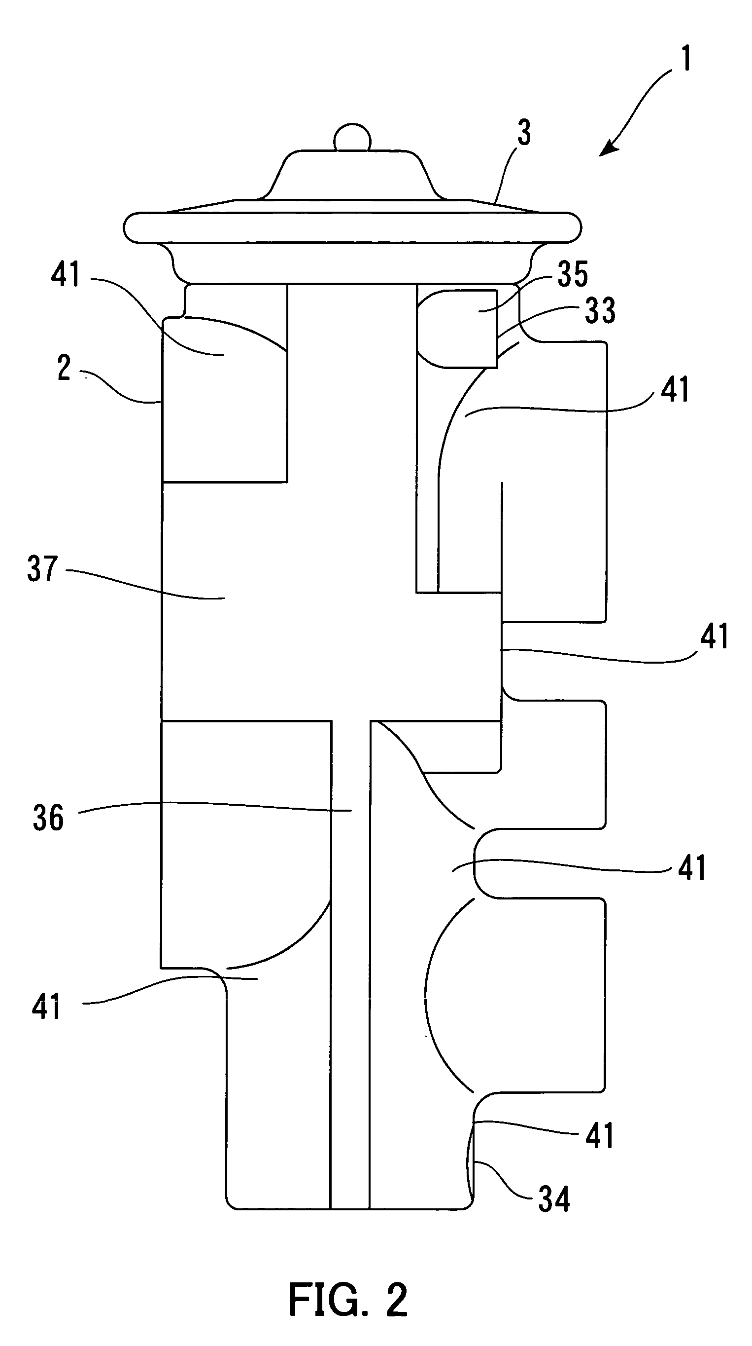
[0060] First of all, a first embodiment of the present invention will be described. In the present embodiment, an expansion valve according to the present invention is embodied as a temperature expansion valve that is applied to a refrigeration cycle for an automotive air conditioner. FIG. 1 is a front view of the expansion valve. FIG. 2 is a left side view of the same. FIG. 3 is a rear view of the same. Further, FIG. 4 is a cross-sectional view taken on line A-A of FIG. 1.

[0061] As shown in FIGS. 1 to 3, the expansion valve 1 has a body 2 formed by die casting of an aluminum alloy, described hereinafter. The body 2 is generally prism-shaped, and has lightening portions for reducing the weight thereof formed all over its side surfaces. A valve section for throttling and expanding refrigerant is formed inside the body 2, and a power element 3 functioning as a temperature-sensing section is provided at a longitudinal end of the body 2.

[0062] As shown in FIG. 4, the ...

Example

Second Embodiment

[0092] Next, a description will be given of a second embodiment of the present invention. It should be noted that an expansion valve according to the present embodiment has a large number of points of construction common to those of the expansion valve according to the first embodiment, and hence component parts approximately identical to those of the first embodiment will be designated by identical reference numerals, and description thereof is omitted. FIG. 11 is a front view of the expansion valve. FIG. 12 is a left side view of the same. FIG. 13 is a rear view of the same. Further, FIG. 14 is a cross-sectional view taken on line C-C of FIG. 11.

[0093] Referring to FIGS. 11 to 13, the expansion valve 201 has a body 202 formed by die casting an aluminum alloy. The body 202 as well is generally prism-shaped, and has lightening portions for reducing the weight thereof formed all over its side surfaces.

[0094] As shown in FIG. 14, in the expansion valve 201, the bal...

Example

Third Embodiment

[0101] Next, a description will be given of a third embodiment of the present invention. It should be noted that an expansion valve according to the present embodiment has approximately the same construction as that of the expansion valve according to the second embodiment, except that the shape of the body is different, and hence component parts approximately identical to those of the second embodiment will be designated by identical reference numerals, and description thereof is omitted. FIG. 15 is a front view of the expansion valve. FIG. 16 is a left side view of the same. FIG. 17 is a right side view of the same. FIG. 18 is a rear view of the same. Further, FIG. 19 is a cross-sectional view taken on line D-D of FIG. 15.

[0102] Referring to FIGS. 15 to 18, the expansion valve 301 has a body 302 formed by die casting an aluminum alloy. Although the body 302 is also generally prism-shaped, it has ear-shaped inflated portions 331 and 332 extending from openings of ...


PUM

PropertyMeasurementUnit
Particle diameteraaaaaaaaaa
Temperatureaaaaaaaaaa

Abstract

To provide an expansion valve capable of enhancing manufacturing efficiency of a body and yield from material, thereby reducing manufacturing costs thereof. According to the expansion valve of the present invention, a body is formed by die casting an aluminum alloy, and hence even when the body has a complicated shape, it is possible to easily manufacture the body. Further, even a valve seat, which is difficult to form by extrusion, can be formed integrally with the body, and hence the manufacturing efficiency of the body can be enhanced. Furthermore, component parts, such as the valve seat and the like, conventionally formed by cutting, are also formed integrally with the body by die casting, and hence it is possible to enhance yield from material to reduce manufacturing costs of the expansion valve.

Description

CROSS-REFERENCE TO RELATED APPLICATIONS, IF ANY [0001] This application claims priorities of Japanese Application No. 2005-060795 filed on Mar. 4, 2005, entitled “EXPANSION VALVE”, No. 2005-212618 filed on Jul. 22, 2005, entitled “EXPANSION VALVE”, No. 2005-356373 filed on Dec. 9, 2005, entitled “EXPANSION VALVE” and No. 2006-012969 filed on Jan. 20, 2006, entitled “EXPANSION VALVE”. BACKGROUND OF THE INVENTION [0002] (1) Field of the Invention [0003] The present invention relates to an expansion valve which is disposed in a refrigeration cycle, for throttling and expanding refrigerant introduced from an upstream side and delivering the refrigerant to a downstream side. [0004] (2) Description of the Related Art [0005] In general, a refrigeration cycle for an automotive air conditioner comprises a compressor that compresses refrigerant circulating through the refrigeration cycle, a condenser that condenses the compressed refrigerant, a receiver that stores the refrigerant circulating...

Claims


Application Information

Patent Timeline
IPC IPC(8): F25B41/04
CPCB22D17/007B22D19/00B22D25/00F16K27/00F25B41/062F25B2341/0683F25B41/335
Inventor SENDO, ISAOMATSUMOTO, MICHIOWATANABE, TAKESHIKUMAKURA, TAKANAO
Owner TGK
Why Eureka
Try Eureka