Nailing mechanism for a packing plates

Inactive Publication Date: 2010-07-15
TU WEN YI
View PDF31 Cites 6 Cited by
  • Summary
  • Abstract
  • Description
  • Claims
  • Application Information

AI Technical Summary

Benefits of technology

[0006]The primary objective of the present invention is to provide a nailing mechanism for a packing plate that are used to automatically assemble a plur

Problems solved by technology

A convention packing plate is manually made by nailing a plurality of first, secon

Method used


Image

  • Nailing mechanism for a packing plates
  • Nailing mechanism for a packing plates
  • Nailing mechanism for a packing plates

Examples


Example

[0030]The present invention will be clearer from the following description when viewed together with the accompanying drawings, which show, for purpose of illustrations only, the preferred embodiment in accordance with the present invention.

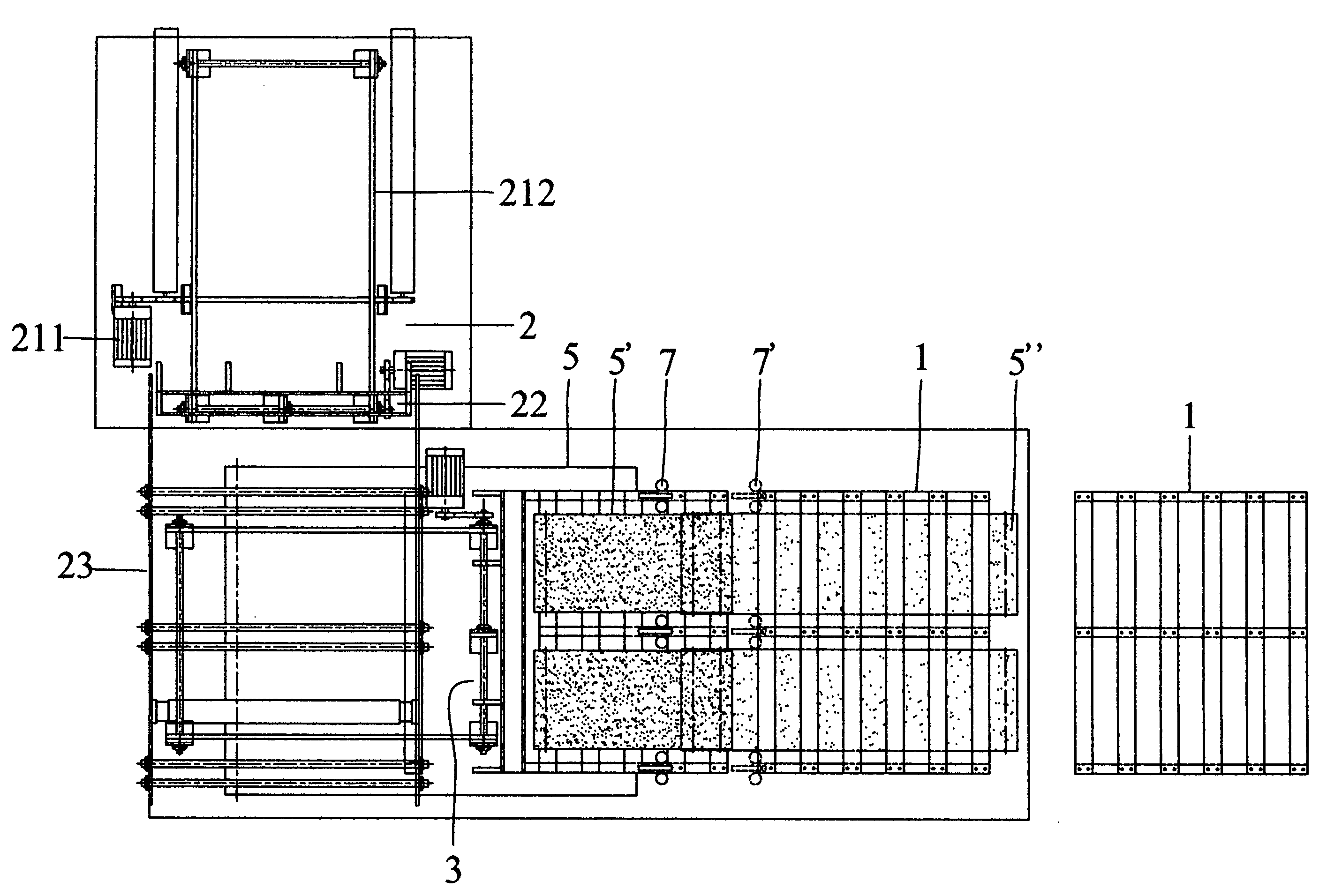
[0031]A nailing mechanism for a packing plate in accordance with the present invention comprises a middle feeding device, an upper feeding device, a lower feeding device, a first conveying belt, a second conveying belt, a third conveying belt, a first push panel, a second push panel, a plurality of first nail guns, and a plurality of second nail guns, wherein the nailing mechanism are used to automatically assemble a plurality of first, second, and third slabs together to make a finished packing plate, thus lowering production costs and enhancing manufacturing efficiency.

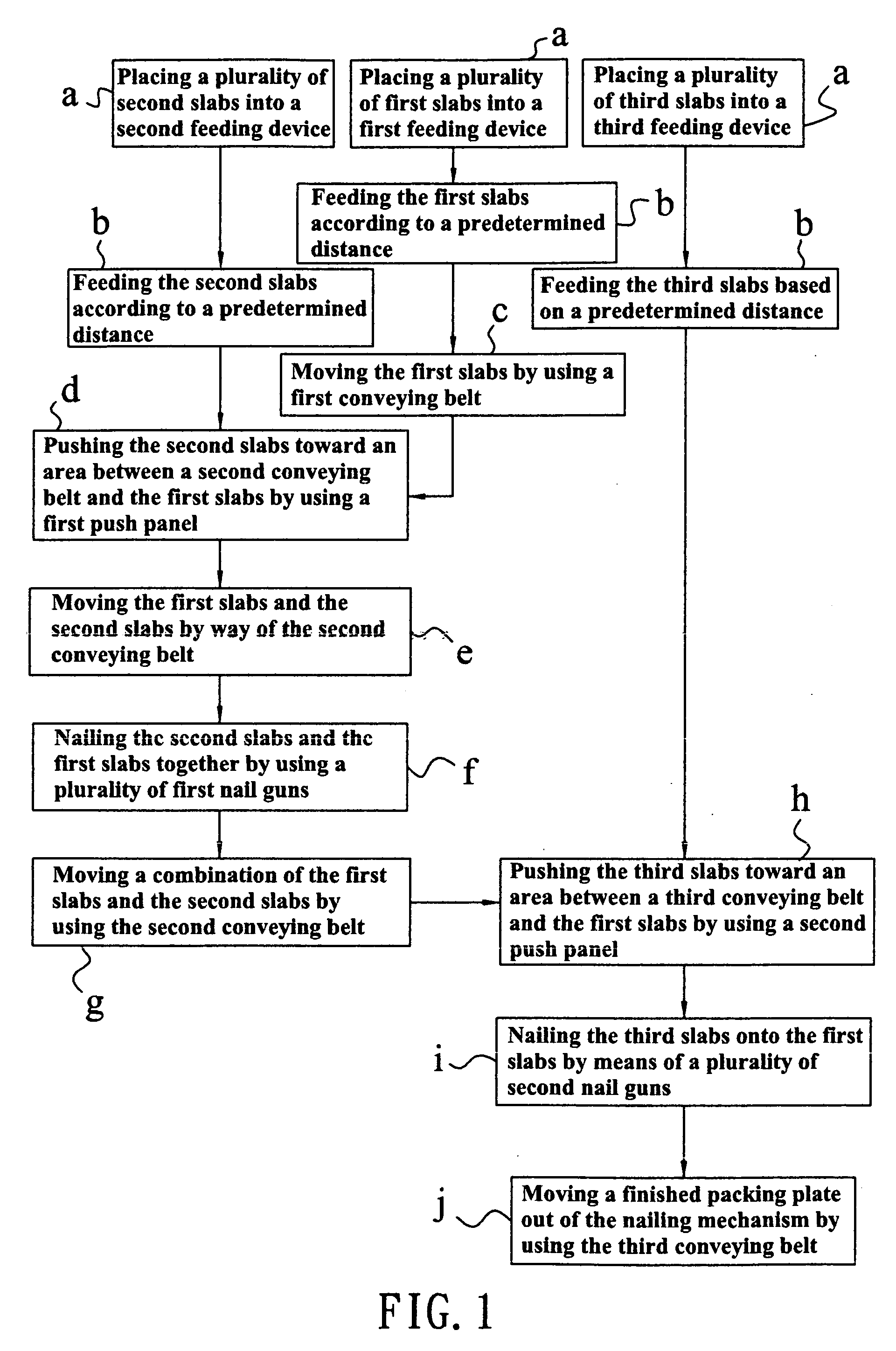
[0032]Referring to FIGS. 1-5, the manufacturing processes of the packing plate of the present invention comprises:

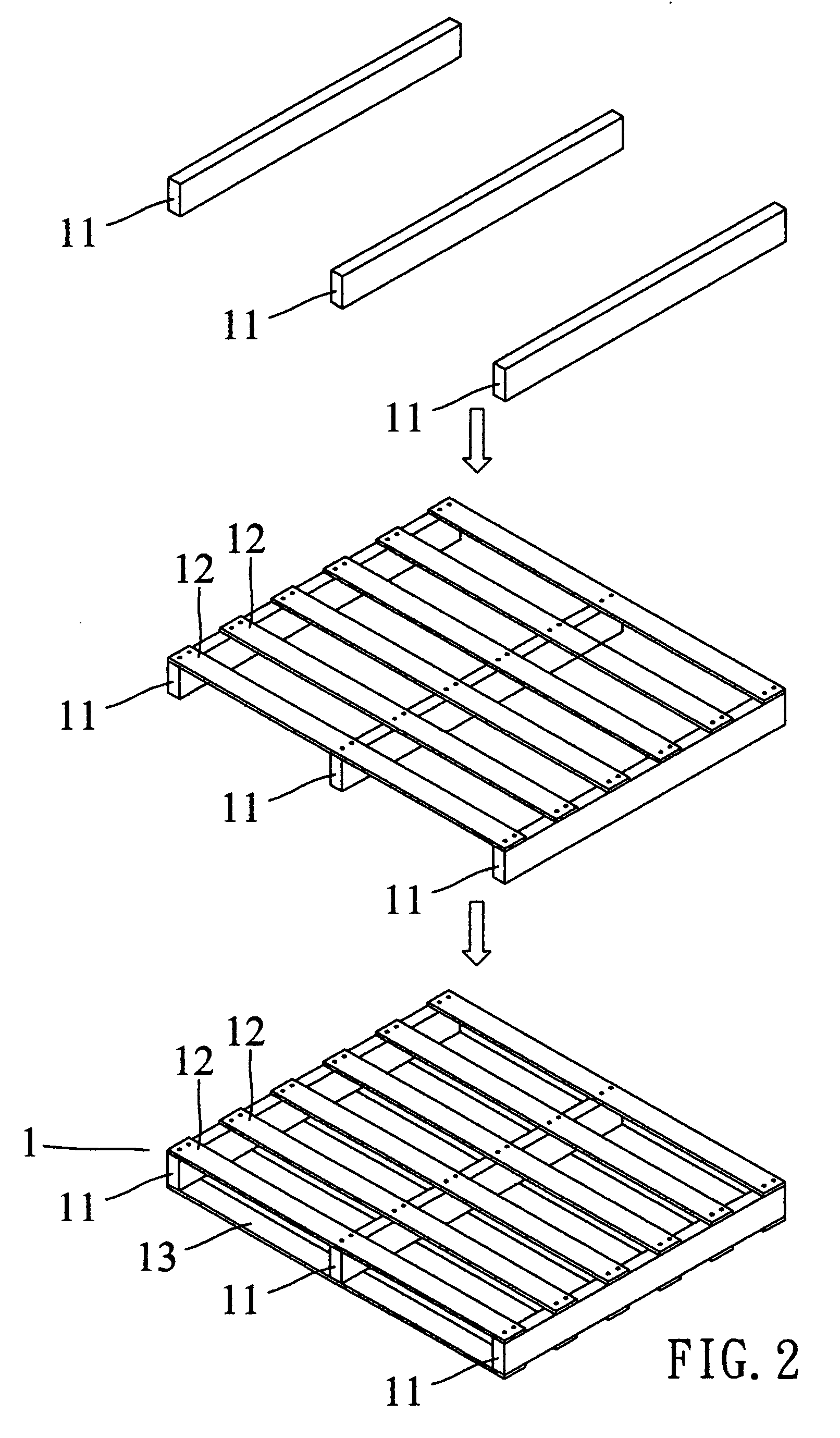
[0033]a. placing a plurality of first slabs 11, second slabs 12,...


PUM


Abstract

A nailing mechanism for a packing plate comprises a middle feeding device, an upper feeding device, a lower feeding device, a first conveying belt, a second conveying belt, a third conveying belt, a first push panel, a second push panel, a plurality of first nail guns, and a plurality of second nail guns, wherein the nailing mechanism are used to automatically assemble a plurality of first, second, and third slabs together to make a finished packing plate, thus lowering production costs and enhancing manufacturing efficiency.

Description

BACKGROUND OF THE INVENTION[0001]1. Field of the Invention[0002]The present invention relates to a nailing mechanism for a packing plate that are used to automatically assemble a plurality of first, second, and third slabs together to make a finished packing plate, thus lowering production costs and enhancing manufacturing efficiency.[0003]2. Description of the Prior Art[0004]A convention packing plate is manually made by nailing a plurality of first, second, and third slabs together, thus consuming time and causing high production cost.[0005]The present invention has arisen to mitigate and / or obviate the afore-described disadvantages.SUMMARY OF THE INVENTION[0006]The primary objective of the present invention is to provide a nailing mechanism for a packing plate that are used to automatically assemble a plurality of first, second, and third slabs together to make a finished packing plate, thus lowering production costs and enhancing manufacturing efficiency.[0007]The nailing mechan...

Claims


Application Information

Patent Timeline
IPC IPC(8): B27F7/02
CPCB27M3/0073Y10T29/53378Y10T29/5397Y10T29/53317Y10T29/5337
Inventor TU, WEN - YI
Owner TU WEN YI
Why Eureka
Try Eureka