Liquid ring pump

Active Publication Date: 2010-01-19
STERLING FLUID SYST GERMANY
View PDF10 Cites 3 Cited by
  • Summary
  • Abstract
  • Description
  • Claims
  • Application Information

AI Technical Summary

Benefits of technology

[0014]Even in single-stage pumps with diagonal through flow, in which in each case only one opening is used on the suction and pressure side, the invention can be used if the respectively unused suction or pressure opening is covered. According to the invention, therefore, complete liquid ring gas pump series, comprising single-stage and multi-stage machines and compressor

Problems solved by technology

In this case, it is not necessary for the remaining open space in the unneeded opening in the control disc to be filled, althou

Method used


Image

  • Liquid ring pump
  • Liquid ring pump
  • Liquid ring pump

Examples


Example

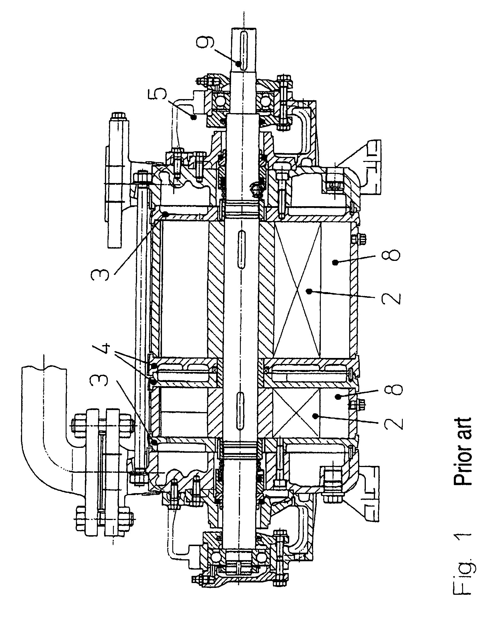
[0025]FIG. 1 shows a conventional two-stage liquid ring gas pump. This has two impellers 2, which are arranged in two working spaces 8 and are carried by a shaft 9. The working spaces 8 are bounded axially by control discs 3, 4. As can be seen, four different control discs are needed.

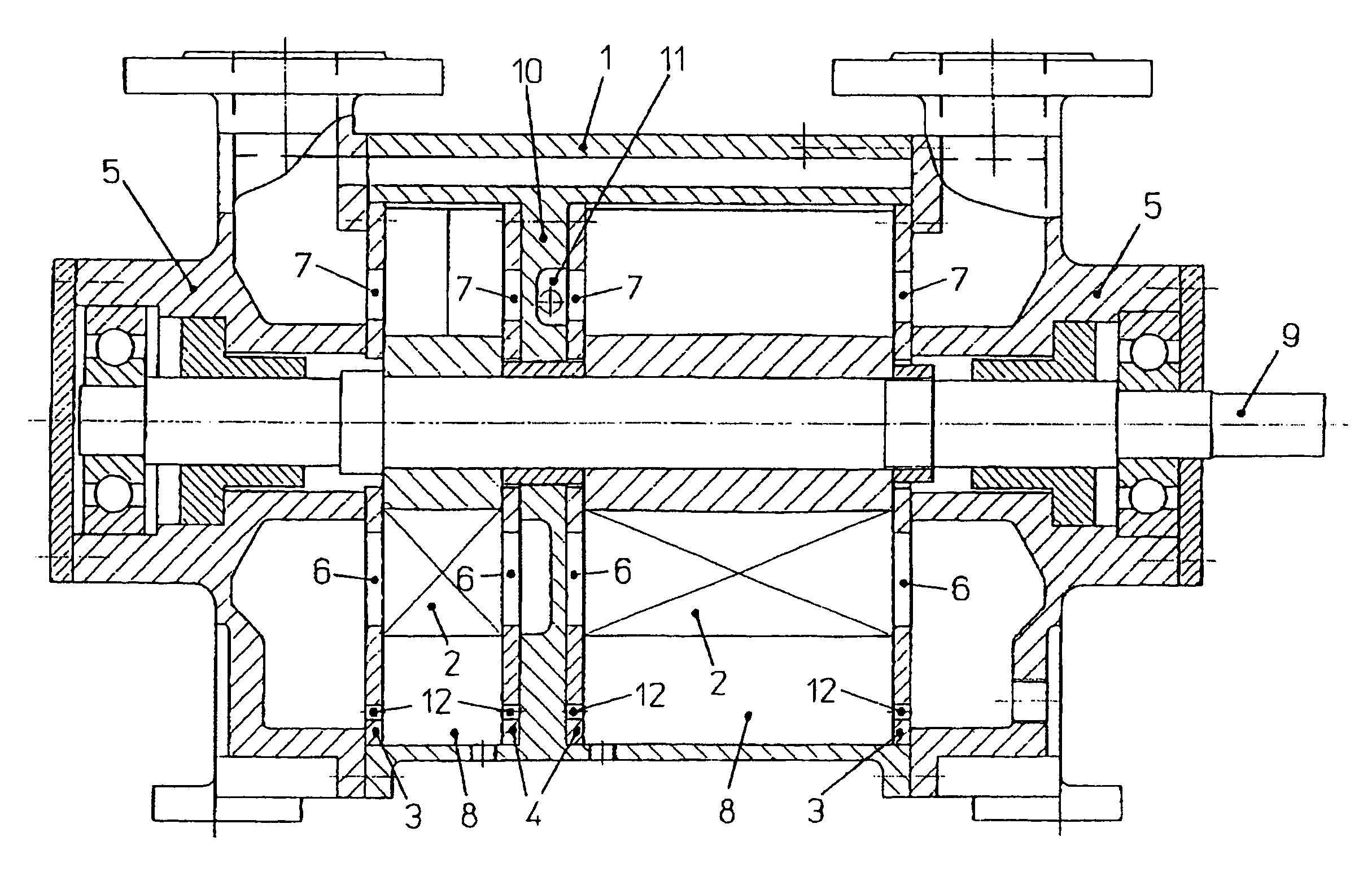
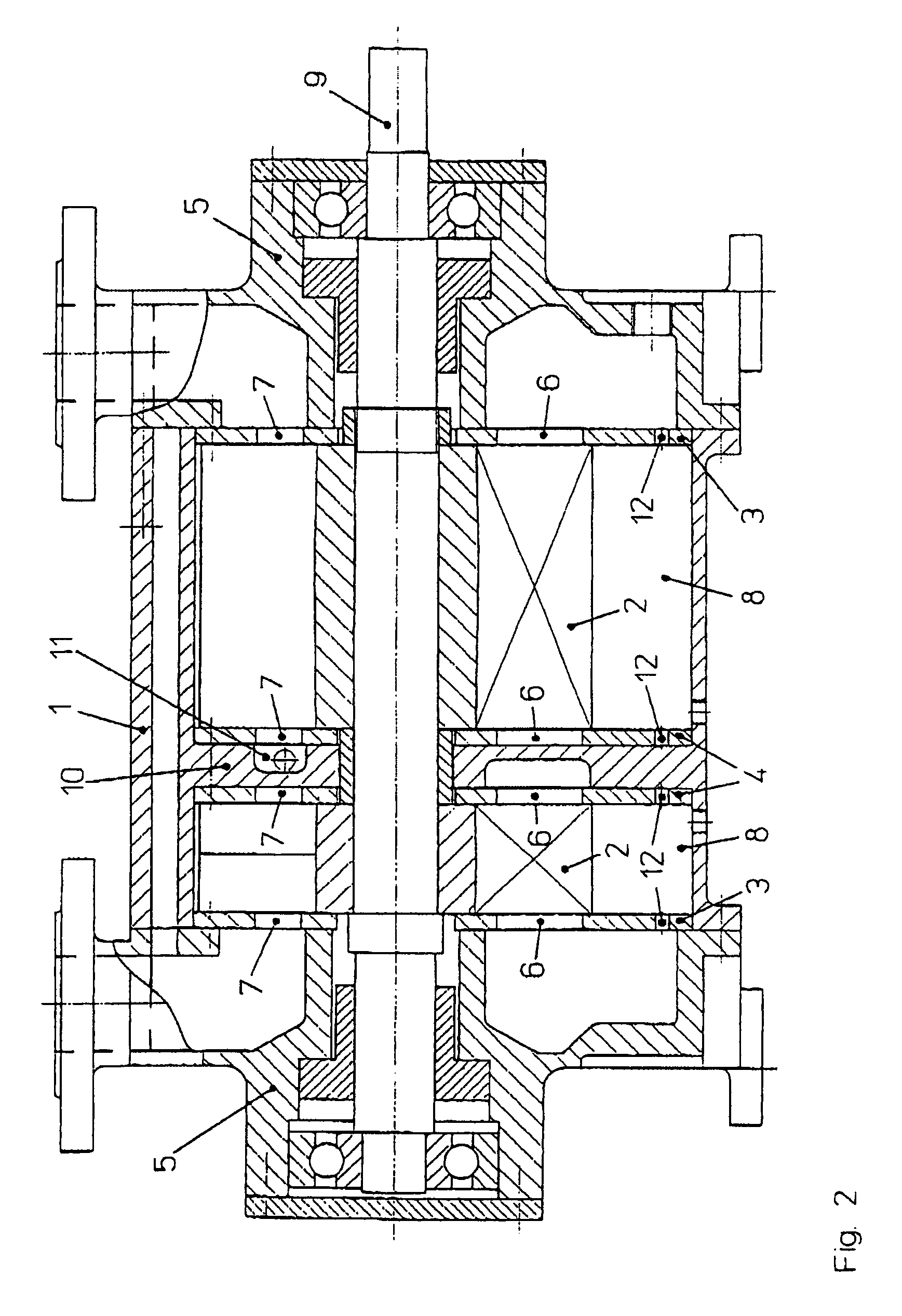
[0026]FIG. 2 shows a pump according to the invention in a similar illustration, in which pump the control discs 3, 4 with the suction openings 6 and pressure openings 7 are formed identically to each another. In this case, the pressure opening 7 of the inner control disc 4 of the left (second) stage, and the suction opening 6 of the inner control disc 4 of the right (first) stage are covered by an intermediate wall 10. The pressure opening of the inner control disc 4 of the right stage is connected via a duct 11 to the suction opening of the inner control disc 4 of the left stage. 12 designates further openings required for the function of the pump.

[0027]FIG. 3 shows a single-stage pump, in which the tw...


PUM


Abstract

Disclosed is a liquid ring pump with one or several stages, each of which comprises a working chamber, an impeller that is eccentrically mounted therein, flat control disks that axially delimit the working chamber on both sides, and ducts or chambers that are located adjacent to the control disks and deliver and discharge the transport gas to and from the working chamber. The inventive liquid ring pump is characterized in that the control disks are embodied in the same manner with identical suction ports and pressure ports while ports that are not needed are covered on the side facing away from the impeller.

Description

BACKGROUND OF THE INVENTION[0001]The invention relates to a liquid ring gas pump having one or more stages, which each have a working space, an impeller eccentrically mounted therein, control discs that bound the working space axially on both sides, and adjacent ducts or chambers for the supply and discharge of the conveyed gas to and from the working space, the control discs being formed identically to each other with identical suction and pressure openings.[0002]In liquid ring gas pumps, an impeller rotates within an eccentrically circulating liquid ring. During the circulation, the liquid ring penetrates to a greater or lesser extent into the cells formed between the vanes of the impeller. As a result, the free volume in the impeller cells is alternately enlarged and reduced. In that region of the revolution in which the cell volume is enlarged, the suction opening, through which the gas to be conveyed is taken into the cells, is located at the end in a control disc. In the end r...

Claims


Application Information

Patent Timeline
IPC IPC(8): F04C19/00F01C21/10
CPCF01C21/108F04C19/007F04C2230/10F04C2230/103F04C2230/21F04C2250/10
Inventor WENCKEBACH, BERNDHEETSCH, SILKEJUNEMANN, ALFONS
Owner STERLING FLUID SYST GERMANY
Why Eureka
Try Eureka