An air treatment system for a confined environment

Active Publication Date: 2021-03-11
TECNOCAD ENG & DESIGN SRL
View PDF0 Cites 2 Cited by
  • Summary
  • Abstract
  • Description
  • Claims
  • Application Information

AI Technical Summary

Benefits of technology

[0008]The object of the present invention is to overcome the technical problems mentioned above. In particular, the object of the invention is to provide an air-treatment system for confined environments, in particular cabins of vehicles operating in hostile environments, characterized by a simpli

Problems solved by technology

This, however, involves two sorts of technical problems; namely:an unnecessary complication of construction, moreover accompanied by an inevitable increase in the production cost; anda non

Method used


Image

  • An air treatment system for a confined environment
  • An air treatment system for a confined environment
  • An air treatment system for a confined environment

Examples


Example

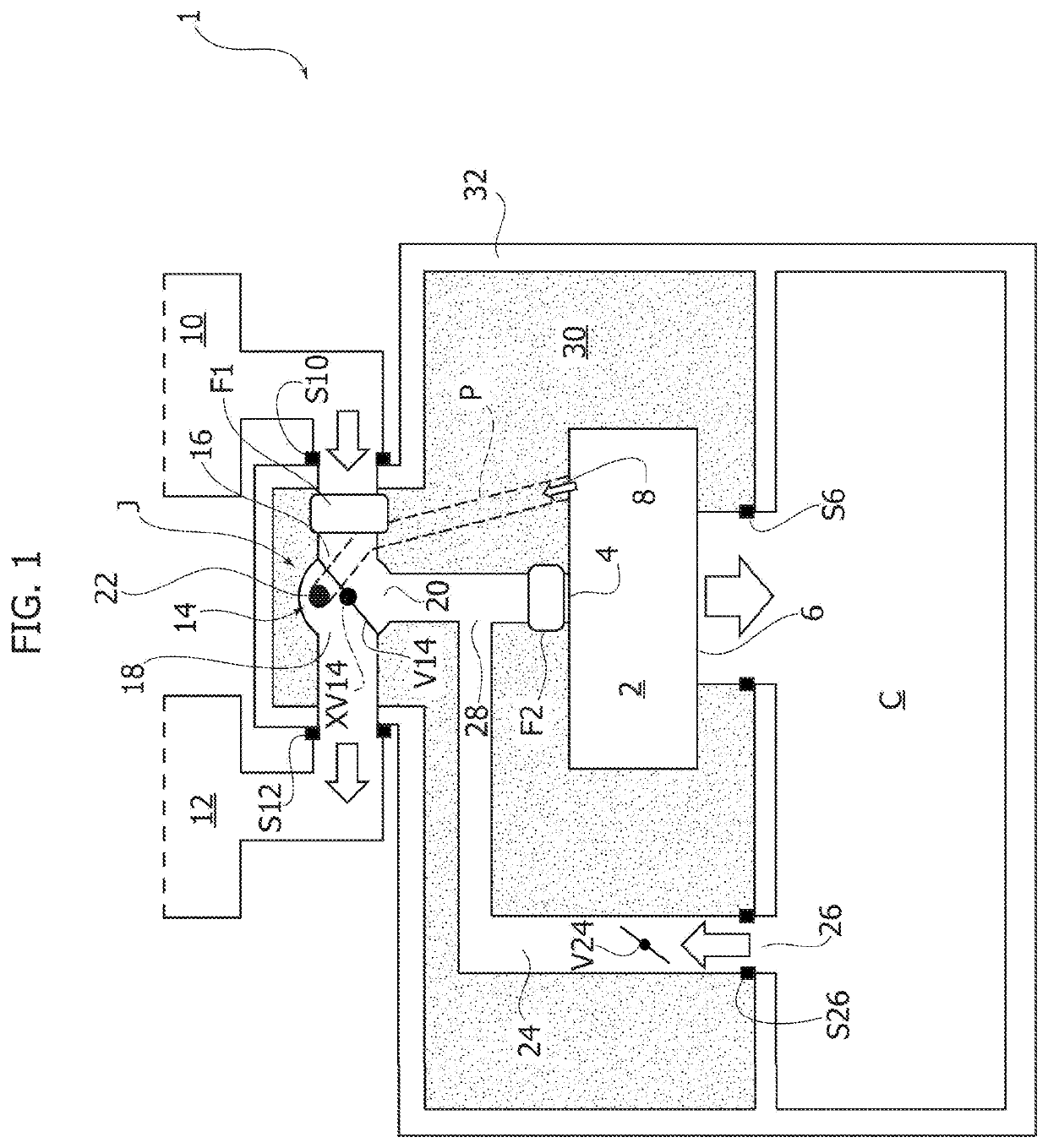
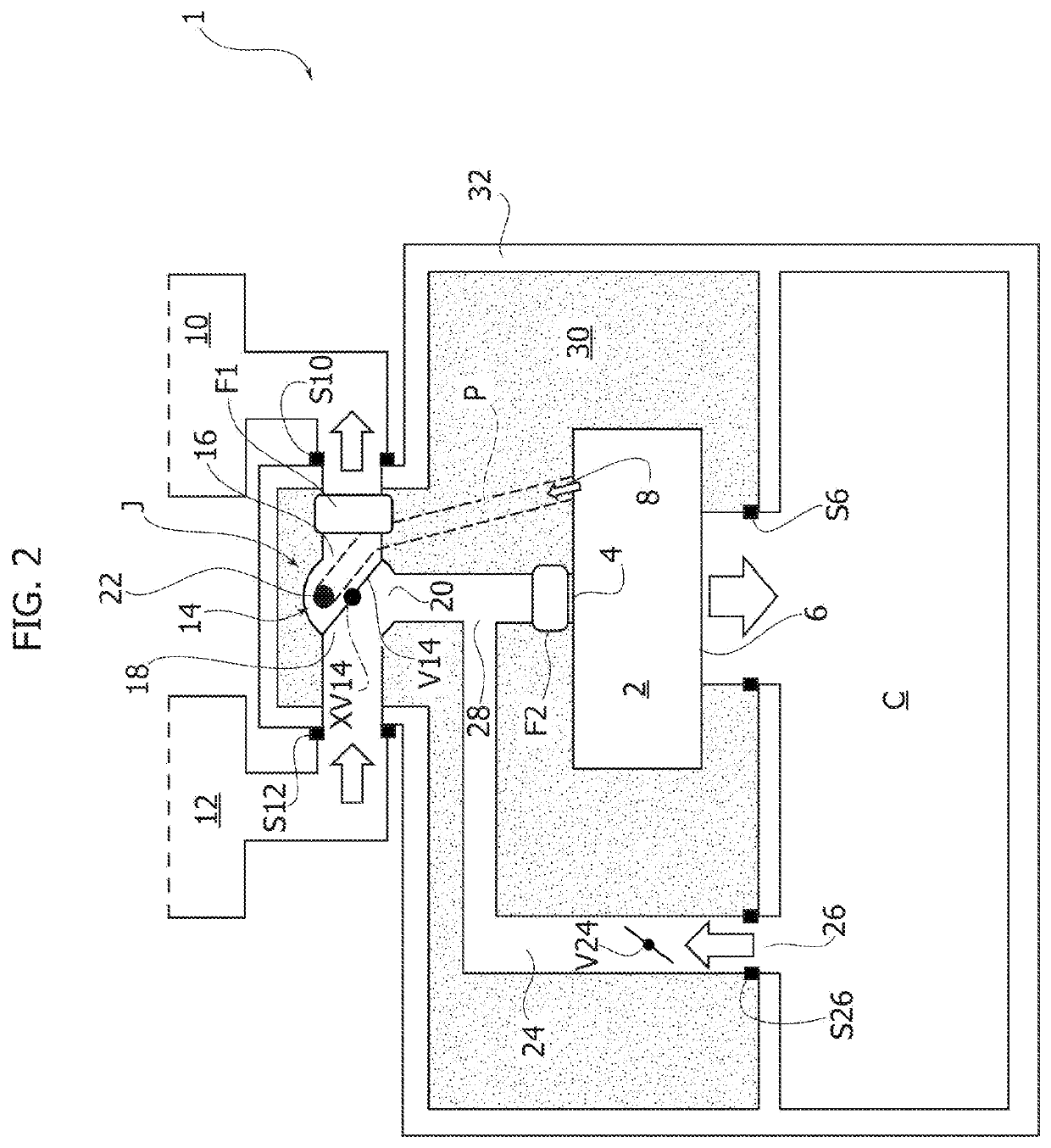
[0021]The reference number 1 in FIGS. 1 and 2 designates as a whole an air-treatment system for a confined environment, in particular the cabin of a vehicle, according to various embodiments of the invention. The system 1 comprises a supply unit 2 including an inlet port 4 and a delivery port 6. The supply unit 2 is configured to intake a flow of air through the port 4 and deliver air through the delivery port 6 to a confined environment C, for example the cabin of a vehicle. In a preferred embodiment for vehicle use, the supply unit 2 is a cabin HVAC (Heating, Ventilation, and Air Conditioning) unit, including a fan as element for intake and delivery of a flow of air through the ports 4 and 6. Preferentially, the supply unit includes—when it is provided as cabin HVAC unit—an evaporator and a heater for the cabin. The fan may be set either inside the unit 2 or on the outside as in the case of the fan F2 in the figures, which is set immediately upstream of the inlet port 4.

[0022]It s...


PUM


Abstract

An air-treatment system for a confined environment, in particular the cabin of a vehicle, includes: a supply unit including an inlet port, a delivery port, and a purge port, the supply unit being configured for delivering air to said confined environment through the delivery port; and a first filtering device having a first filtration level, and a second filtering device having a second filtration level, each of the first and second filtering devices being arranged in fluid communication with the inlet port of said supply unit at a circuit node. A single flow-control valve determines inlet flow through one or other of the filtering devices.

Description

FIELD OF THE INVENTION[0001]The present invention relates to systems for treating air for confined environments, in particular vehicle cabins. The invention has been developed with particular reference to air-treatment systems that equip vehicles operating in hostile environments (i.e., environments that are polluted, contaminated, or contain noxious dust).PRIOR ART[0002]Known air-treatment systems for confined environments, such as cabins of vehicles operating in hostile environments, generally include a supply unit, which is configured for administering air to the confined environment, and a pair of filtering devices with different performance features. Normally, a first filtering device ensures a first filtration level (typically, this is a filtering device with filter element that conforms to EU Category 4 of EN 15695 standard), whilst a second filtering device ensures a second filtration level, lower than the first (typically, this is a filtering device with filter element that...

Claims


Application Information

Patent Timeline
IPC IPC(8): B60H3/06
CPCB60H3/0658B60H1/00378B60H1/00414B60H1/00685B60H3/0633B60H3/0641B60H2001/00085
Inventor TOPPANI, NICOLAS
Owner TECNOCAD ENG & DESIGN SRL
Why Eureka
Try Eureka