Vertical oil separator

a vertical oil separator and oil separator technology, applied in refrigeration, lighting and heating apparatus, refrigeration and liquid storage, etc., can solve the problems of reducing the efficiency of the condenser and evaporator functions, lubricating oil serves no useful purpose outside the compressor, and oil does not have as good heat transfer capability, so as to achieve a high degree of centrifugal action and convenient service

Inactive Publication Date: 2006-09-07
WESTERMEYER GARY W
View PDF22 Cites 36 Cited by
  • Summary
  • Abstract
  • Description
  • Claims
  • Application Information

AI Technical Summary

Benefits of technology

[0008] Another object is to provide an efficient, easily serviced and economic oil system for a compressor driven refrigeration / chiller system. Thus, in another aspect of the invention the incoming high pressure oil-refrigerant gas mixture is given a high degree of centrifugal action to separate out the oil on a collection device in an upper inlet section, and such turbulent action is substantially eliminated from a lower liquid oil accumulator section by a dividing baffle

Problems solved by technology

It is clear that the lubricating oil serves no useful purpose outside the compressor.
Oil does not have as good heat transfer capability as the refrigerant and will reduce the efficiency of the condenser and evaporator functions.
Such oil separators, as discussed in U.S. Pat. Nos. 4,478,050; 4,506,523; 5,133,671; and 5,271,245, are known for separating oil from the high side refrigerant gas and oil mixture, but these and other prior oil separators are deficient in performance, cost, size, system complexity and other limiting factors.

Method used


Image

  • Vertical oil separator
  • Vertical oil separator
  • Vertical oil separator

Examples


Embodiment Construction

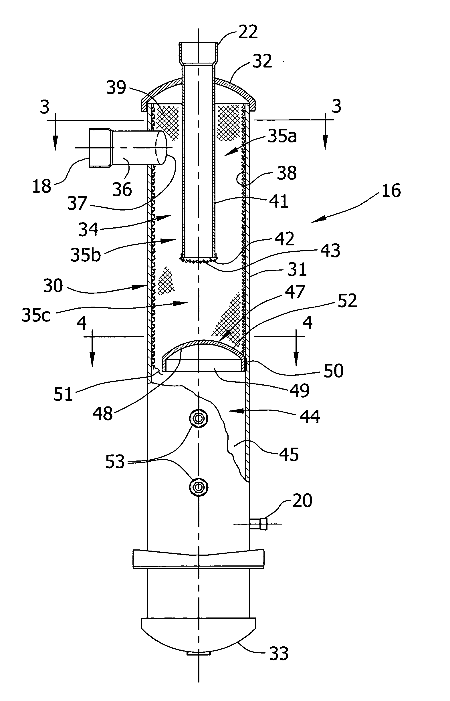
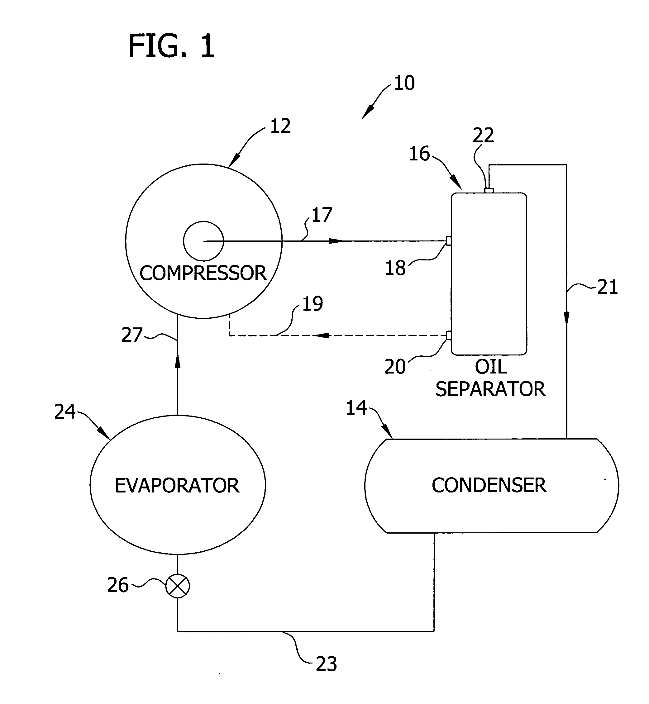
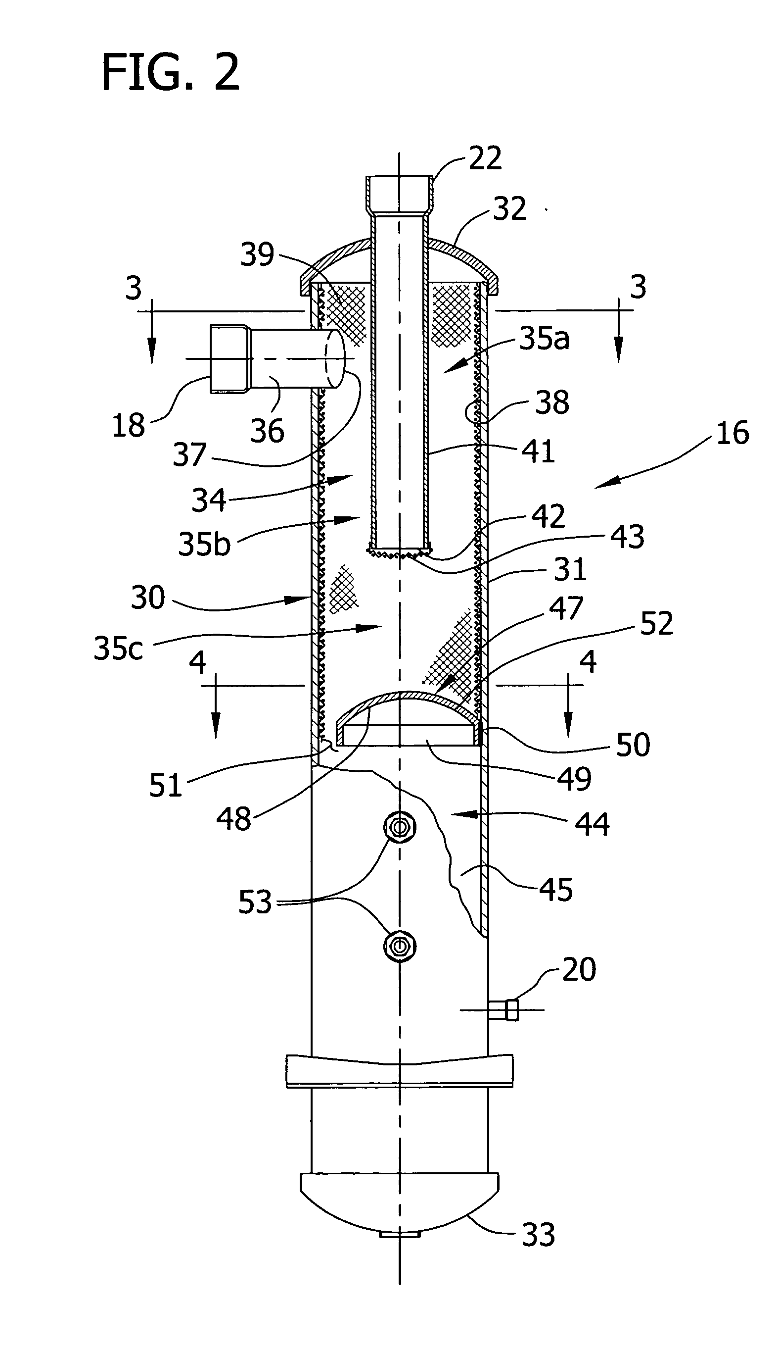
[0023] For the purposes of disclosure, a closed refrigeration or chiller system 10 includes a compressor 12 connected on its high pressure outlet side to a condenser 14 through an oil separator 16 embodying the invention to be described. Typically the compressor 10 requires a large amount of lubricating and cooling oil in operation, and such oil is entrained in the hot compressed refrigerant to form an oil-gas mixture that is discharged on the compressor high side through conduit 17 to the oil separator inlet 18. It has been reported that the oil content in the oil and refrigerant gas mixture from a chiller system compressor is over 50,000 ppm (parts per million). The compressor 12 is also in fluid communication with the oil separator 16 through an oil return conduit 19 from oil outlet 20 through which oil is returned to and maintained in the compressor at a preselected level by a conventional oil level regulator (not shown) or the like. The condenser 14 is connected in fluid commun...


PUM


Abstract

A vertical oil separator for separating oil from a refrigerant gas and oil mixture on the high side of a refrigeration / chiller system comprising, a vertical housing having an upper chamber with a cylindrical sidewall and tangentially oriented inlet for the refrigerant gas and oil mixture, said upper chamber having a refrigerant gas outlet therefrom, said housing also having a lower chamber below the upper chamber with an oil outlet therefrom, a baffle constructed and arranged in said housing to define said upper and lower chamber, at least one oil filter in said upper chamber for removing oil out of the mixture and transferring such oil downwardly from the upper chamber.

Description

FIELD OF THE INVENTION [0001] The present invention relates generally to the commercial and industrial refrigeration art. More particularly, the invention is directed to improvements in vertical oil separators for efficiently separating oil and refrigerant gas on the high side of a refrigeration system. BACKGROUND OF THE INVENTION [0002] The maintenance of lubricating oil in a refrigeration system compressor is critical to its efficient operation and life span. Clearly the compressor is the principal driving force in any refrigeration or chiller system—it compresses refrigerant gas and discharges it on its high pressure side to a condenser in which the gas is condensed to a liquid phase, and thence it passes to an evaporator or like cooling coil through an expansion device reducing the refrigerant's pressure and permitting absorption of heat and expanding the liquid phase gas back to a gaseous phase on the low suction side of the compressor. All types of compressors—reciprocating, s...

Claims


Application Information

Patent Timeline
Patent Type & Authority Applications(United States)
IPC IPC(8): F25B43/02F25B43/00
CPCF25B43/02F25B2400/02
Inventor WESTERMEYER, GARY W.
Owner WESTERMEYER GARY W
Why Eureka
Try Eureka