Electro-magnetic clamp for gripping a shaft

a technology of magnetic clamping and shaft gripping, which is applied in the direction of rigid shaft couplings, mechanical equipment, filament handling, etc., can solve the problems of high wear and other drawbacks of the type of system, and the complexity of the system is relatively high

Inactive Publication Date: 2006-09-07
BLUE S4
View PDF21 Cites 3 Cited by
  • Summary
  • Abstract
  • Description
  • Claims
  • Application Information

AI Technical Summary

Benefits of technology

[0007] In order to actuate the grippers, a pair of opposing plungers is provided for contacting the inner sleeve of each gripper so as to urge the inner sleeve inwardly towards the centre of the body, so as to release the shaft. The grippers are recessed into the clamp body. The outer sleeve of each gripper is fixed in position, by abutting against a shoulder within the interior of the clamp body. The inner sleeve can move axially within a pocket inboard of the shoulder. The plungers are each operatively connected to an arm extending outwardly from the body, the arm mounted to the body for sliding movement in a direction axial to the shaft. For example, the arm may be engaged to the body by means of one or more guide pins. Conveniently, the arms include an opening to permit the shaft to pass through the arm, such that the arms may be positioned on either end of the body in a generally central position. Drawing the arms towards each other will thus urge the plungers inwardly towards each other, thereby releasing the shaft so as to slide and rotate freely within the clamp body, while urging the arms apart from each other has the opposite effect. It will be readily seen that the invention may work equally well in the reverse direction, whereby the grippers operate in the reverse direction and urging the arms apart would serve to grip the shaft to the clamp body.

Problems solved by technology

However, this type of system is subject to a high level of wear and other drawbacks.
Other systems have been proposed, all of which involve a relatively high degree of complexity.

Method used


Image

  • Electro-magnetic clamp for gripping a shaft
  • Electro-magnetic clamp for gripping a shaft
  • Electro-magnetic clamp for gripping a shaft

Examples


Embodiment Construction

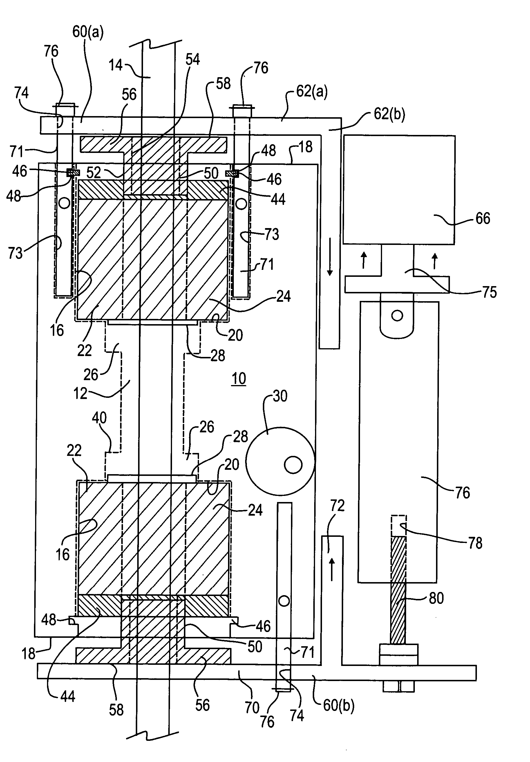
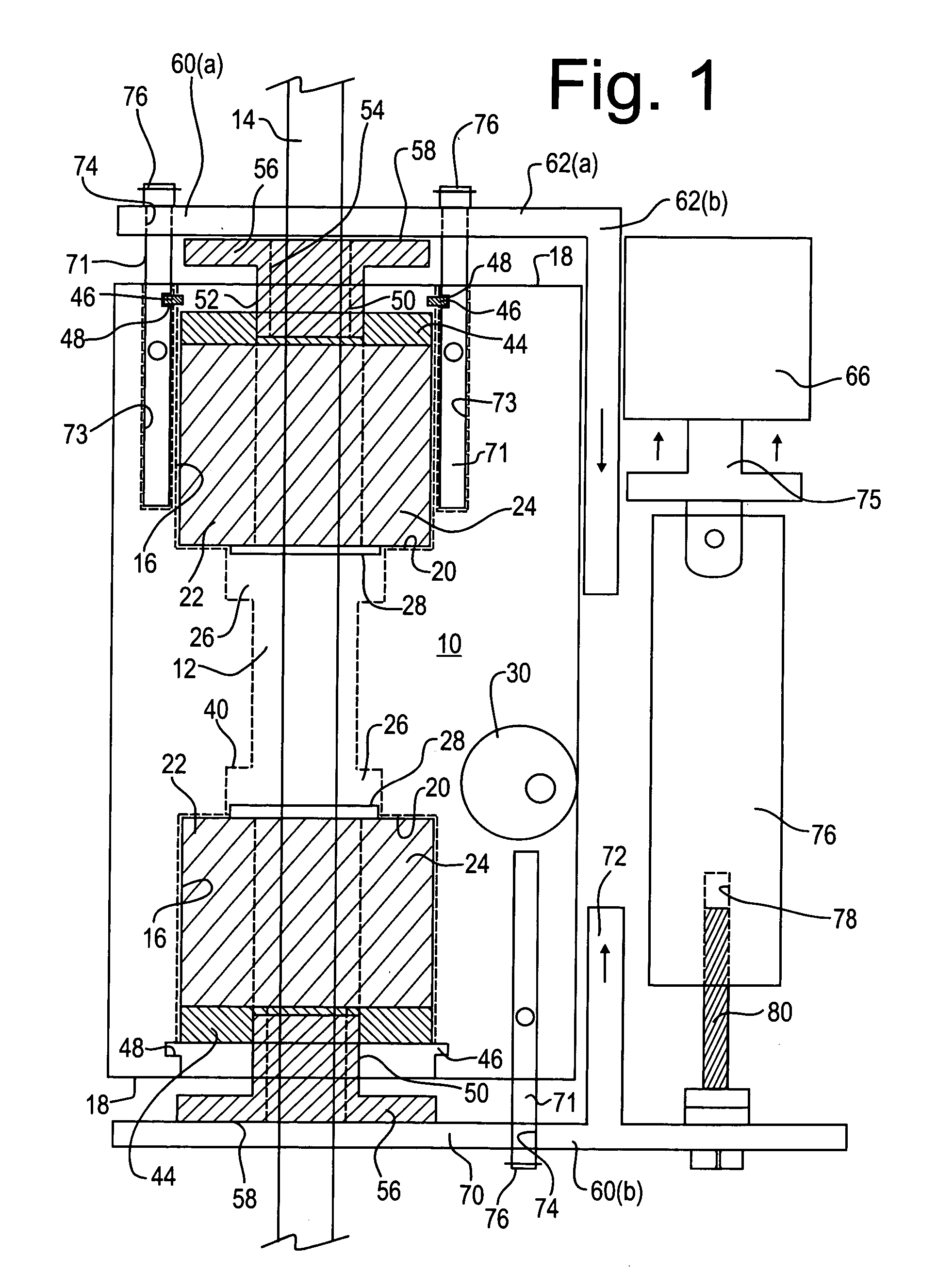
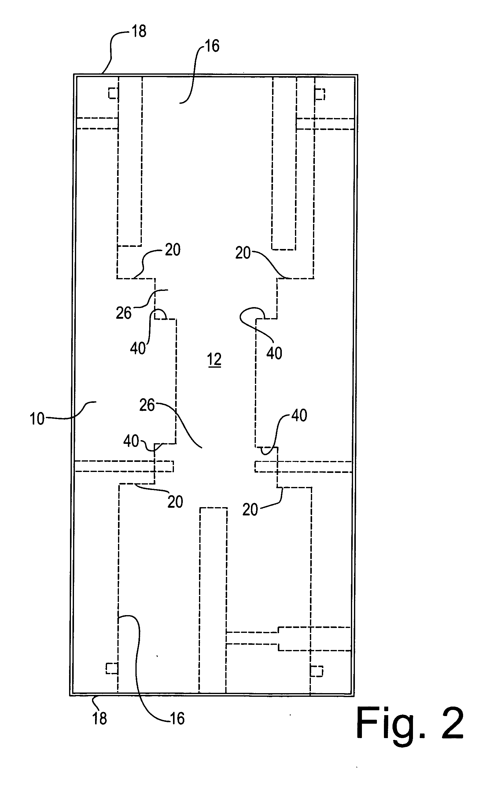
[0017] Referring to the Figures, the clamp body 10 comprises a suitable rigid material, such as a metal such as stainless steel or aluminum, or injection-molded plastic. The body includes a central bore 12 for receiving the shaft 14 in a manner which permits the shaft to slide and rotate freely within the bore when the clamp is in the released position. The bore is symmetrical about its elongate axis, with widened cylindrical recesses 16 at each of its opposed, outboard ends to receive a pair of opposed grippers 24, described below. The recesses 16 open to the opposed ends 18 of the body. The base of each recess 16 is inwardly stepped and comprises an annular shoulder 20 for abutting the outer sleeve 22 of a gripper 24, and a recessed pocket 26 to receive the inner sleeve 28 of gripper 24 to permit a degree of axial movement of the inner sleeve 28 relative to the outer sleeve 22 which is fixed in position. Protruding outwardly from opposing positions on either side of the body is a ...


PUM


Abstract

A clamp for locking engagement with a shaft includes a body having a bore for slideably receiving a shaft, with opposing grippers recessed into the body coaxial with the shaft. The grippers each include inner and outer sleeves displaceable relative to each other, with the outer sleeves being retained by shoulders within the body and the inner sleeves being slideable within a pocket for selectively releasing and gripping the shaft. A pair of opposing plungers selectively displaces the inner sleeves, the plungers each being associated with a slideable arm for coordinated gripping and release of the shaft. The arms are drawn together or apart by an actuator such as a solenoid. The clamp is intended to be fastened to a component, for permitting the component to selectively grip a shaft, or release the shaft for slideable and / or rotateable movement relative to the shaft, such as an optical instrument for testing of patient's eyes which when fastened must tightly grip a shaft to prevent rotation and slideable movement, but which when released must permit free movement relative to the shaft.

Description

FIELD OF THE INVENTION [0001] The invention relates to a releasable clamp for gripping a shaft, for holding a component in a selected fixed position relative to a shaft. BACKGROUND OF THE INVENTION [0002] Mechanical and electro-mechanical devices for holding a component in position in relation to a shaft have applications in many fields. For example, an optical device for measuring a patient's eyes must be precisely positioned in relation to the patient, requiring that the device be freely moveable along a shaft until it reaches the correct position, at which time it must be clamped to the shaft in a releasable fashion but which holds it firmly in place. Numerous other applications exist for a clamp which releasably holds a component in a fixed position along a shaft, but which may be readily released to permit either sliding or rotary movement or both. Existing clamps may comprise a clamp body which supports a pair of angled plates having an aperture therethrough, the plates being ...

Claims


Application Information

Patent Timeline
Patent Type & Authority Applications(United States)
IPC IPC(8): B65H59/10
CPCF16D1/09
Inventor SWOFFER, DERRICK
Owner BLUE S4
Why Eureka
Try Eureka