Electronic door system with a lin-subbus

a technology of electronic door system and subbus, which is applied in the direction of electrical device connection, cable arrangement between relatively moving parts, etc., can solve the problems of undesirable increase in product number of wire harnesses, increase in mass, increase in mass, etc., and achieve the effect of reducing the number of lines and reducing the weight of the wire harness

Active Publication Date: 2006-09-07
YAZAKI CORP
View PDF9 Cites 23 Cited by
  • Summary
  • Abstract
  • Description
  • Claims
  • Application Information

AI Technical Summary

Benefits of technology

[0009] With the above-described problems taken into consideration, the present invention is proposed and it is an object of the present invention to provide an electronic door system in which the functions of a usual ECU are distributed to respectively standardize the functions to individual functions and a wire harness can be simplified, the number of lines can be decreased and the weight of the wire harness can be reduced, and a harness system for a vehicle using the electronic door system.
[0010] Further, it is another object of the present invention to provide an electronic door system that can flexibly meet the change (difference in specification such as design, grade, etc.) of functions in an electrical load parts side related to a door and a harness system for a vehicle using the electronic door system.

Problems solved by technology

Firstly, when the specifications and functions of electrical load parts related to a door change, a wire harness connected to each ECU needs to be changed.
Thus, the kinds and product numbers of wire harnesses are undesirably increased.
As a result, a mass is undesirably increased.
Thirdly, owing to the centralized control by the ECUs, the increase of the functions of the electrical load parts related to the door undesirably causes the ECUs to be enlarged, the mass to be increased (the deterioration of a fuel efficiency and a traveling performance) and loading characteristics to be deteriorated.
Consequently, the number of development processes is inconveniently increased and the number of specification adding and changing processes is undesirably increased.

Method used


Image

  • Electronic door system with a lin-subbus
  • Electronic door system with a lin-subbus
  • Electronic door system with a lin-subbus

Examples


Embodiment Construction

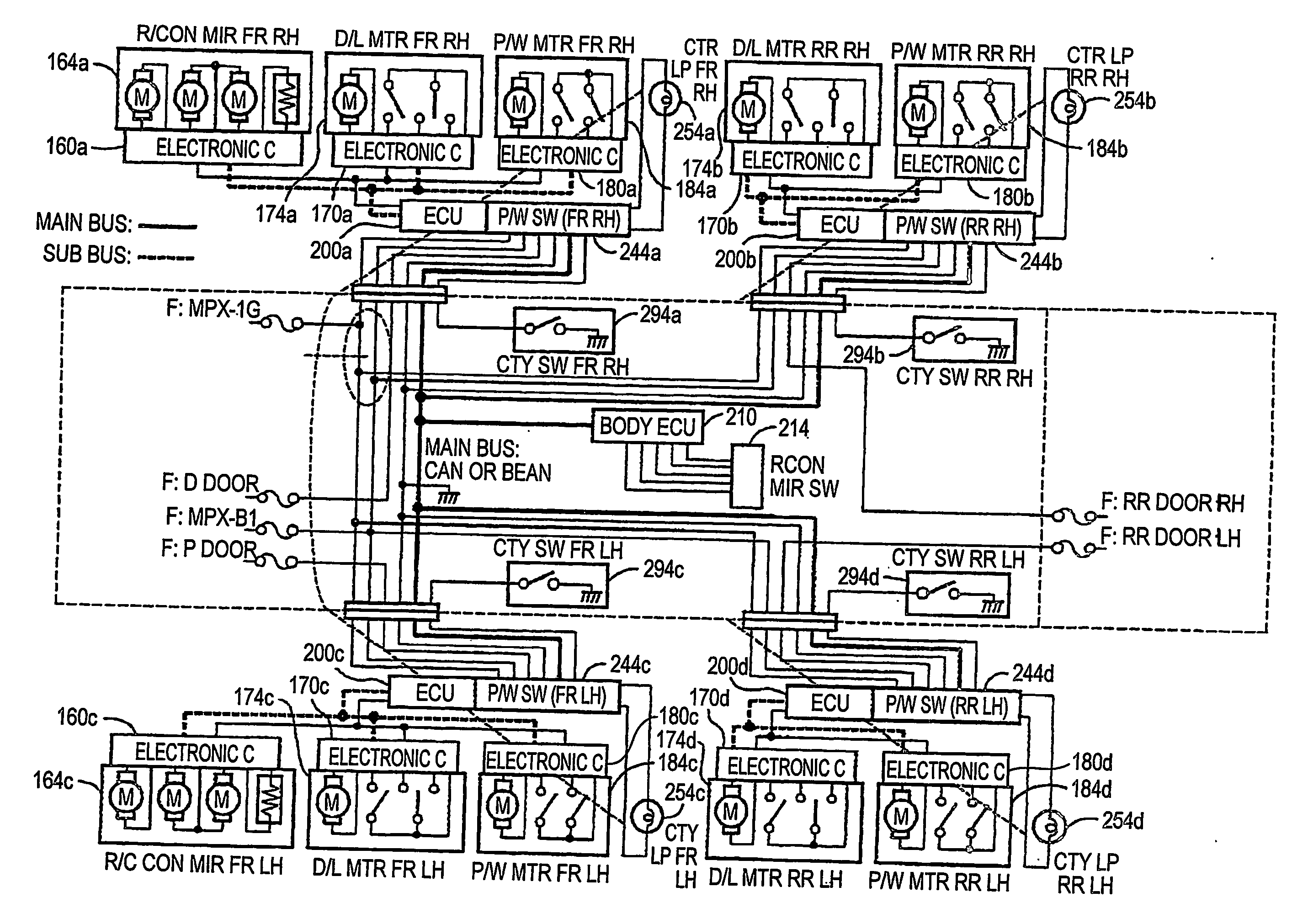
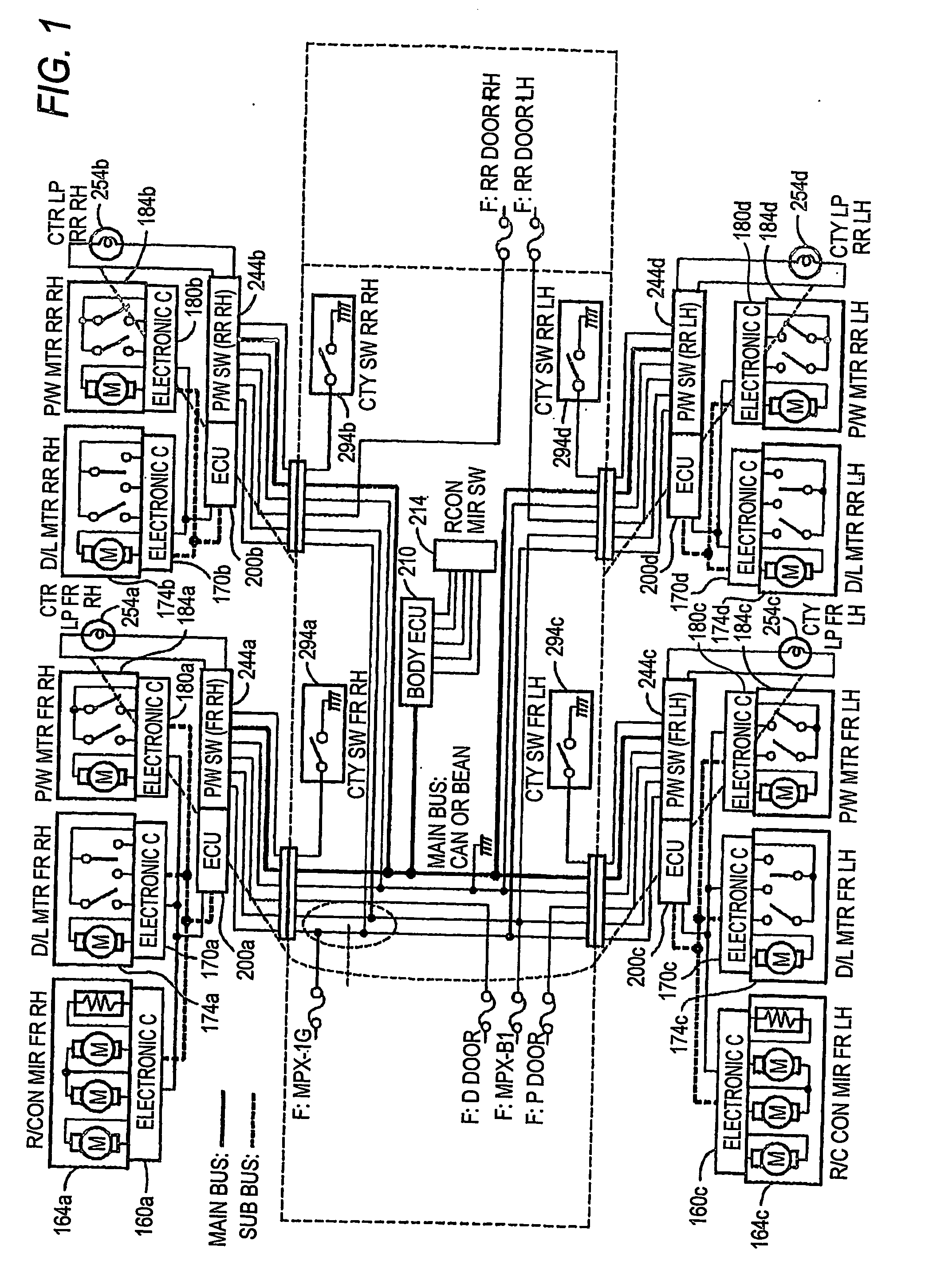
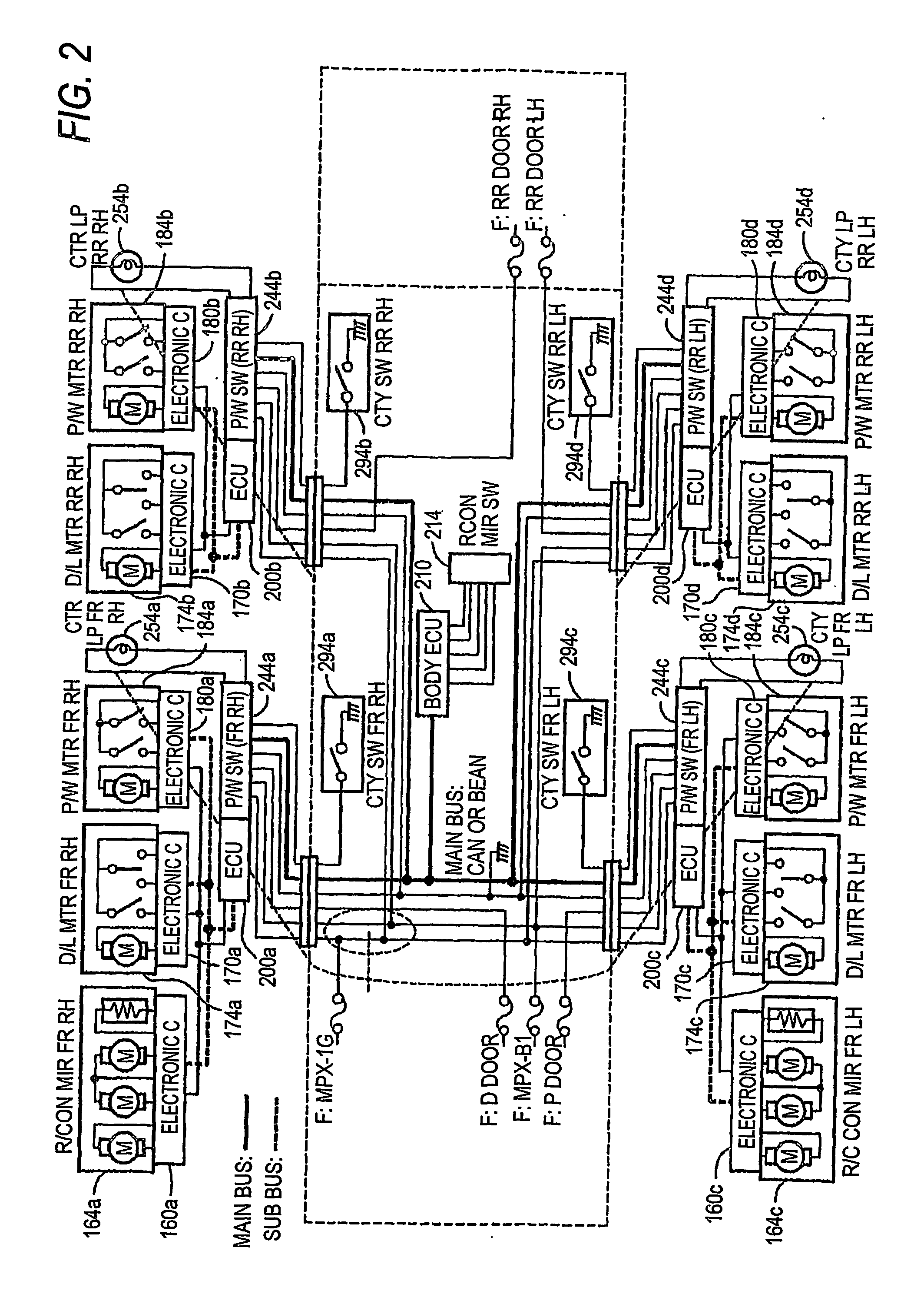
[0054] Now, embodiments of the present invention will be described in detail by referring to the accompanying drawings.

[0055] Before an electronic door system according to the embodiment of the present invention is described, electronic connectors and auxiliary equipment modules used in the electronic door system will be initially described.

[0056]FIG. 3 is a functional block diagram showing a basic concept of the electronic connector in an embodiment of the present invention. An electronic connector 110 directly connected to the connector of a sensor 114 includes a communication part 111, a control part 112 and an I / O part 113 mounted on an electronic board contained therein. An electronic connector 120 directly connected to a switch SW124 also includes a communication part 121, a control part 122 and an I / O part 123 mounted on an electronic board contained therein. An electronic connector 130 directly connected to a load (lamp, motor, etc.) 134 includes a communication part 131, ...


PUM


Abstract

Load type electrical parts incorporated in auxiliary machine modules 164a to 184a are driven by electrical connectors 160a to 180a having communicating units, control units and load driving units mounted on electronic boards. An electronic door control unit 200a connected to a sub bus connected to the electrical connectors 160a to 180a converts the communication protocol of a control signal of the load type electrical parts received from a LAN in a vehicle serving as a main bus of the vehicle to the communication protocol of the sub bus and transmits the protocol converted control signal to the electrical connectors 160a to 180a. Further, sensors or switches in the auxiliary machine modules 164a to 184a output signals to the control units.

Description

TECHNICAL FIELD [0001] The present invention relates to an electronic door system for driving electrical parts for a vehicle mounted on the door of the vehicle and a harness system for a vehicle using the electronic door system. BACKGROUND ART [0002]FIG. 10 is a circuit diagram showing an electronic door system in a vehicle in a related art. The electronic door system of FIG. 10 shows an example of a vehicle having four doors. Door ECUs (Electronic Control Unit) 200a to 200d are respectively mounted on doors. The four door ECUs 200a to 200d are connected together by a LAN (Local Area Network) (main bus) communicated by a protocol such as a CAN (Controller Area Network) or a BEAN (Body Electronics Area Network) or the like. [0003] The right front door ECU 200a controls a right front outer (remote control) mirror module 264a disposed in the door, a right front door lock module 274a, a right front power window module 284a, a right front power window switch module 244a, a right front cu...

Claims


Application Information

Patent Timeline
Patent Type & Authority Applications(United States)
IPC IPC(8): B60L1/00B60R16/02B60R16/03H01R13/66H02G3/38H02G11/00
CPCB60R16/0315
Inventor NAGASAWA, KAZUMIOZAKI, TOSHIAKISHIMIZU, NORIHITO
Owner YAZAKI CORP
Why Eureka
Try Eureka