Eureka AIR delivers breakthrough ideas for toughest innovation challenges, trusted by R&D personnel around the world.

Hybrid-phased communication array

Inactive Publication Date: 2006-09-07
UNITED STATES OF AMERICA THE AS REPRESENTED BY THE SEC OF THE ARMY
View PDF15 Cites 0 Cited by
  • Summary
  • Abstract
  • Description
  • Claims
  • Application Information

AI Technical Summary

Benefits of technology

[0014] Yet another object of the present invention is provide an array of communication modules with each module of the array having a respective low powered T/R element which effectively

Problems solved by technology

As the distance of the low noise amplifier 28 from the radiating e

Method used


Image

  • Hybrid-phased communication array
  • Hybrid-phased communication array
  • Hybrid-phased communication array

Examples


Example

DETAILED DESCRIPTON

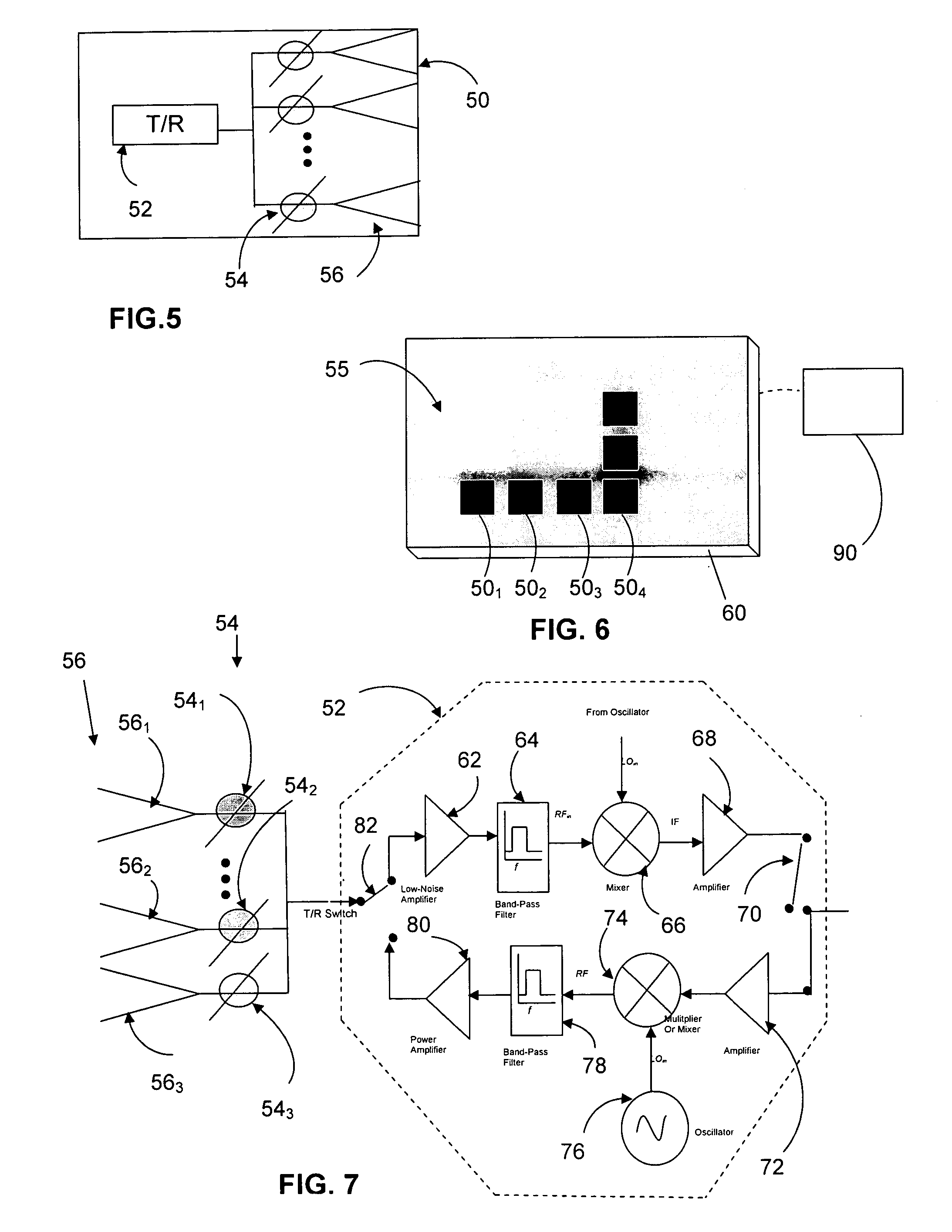
[0025] With reference to FIG. 5, a communication module 50 of the present invention has a transmit / receive module 52 that connects to a row 54 of phase elements. Each phase element in the row 54 of phase elements is connected to a corresponding radiating element in a row 56 of radiating elements.

[0026] In FIG. 6, a communication array 55 has a plurality of communication modules 501, 502, 503, 504, etc., that are positioned above substrate 60. The array is electrically connected to signal processing electronics 90.

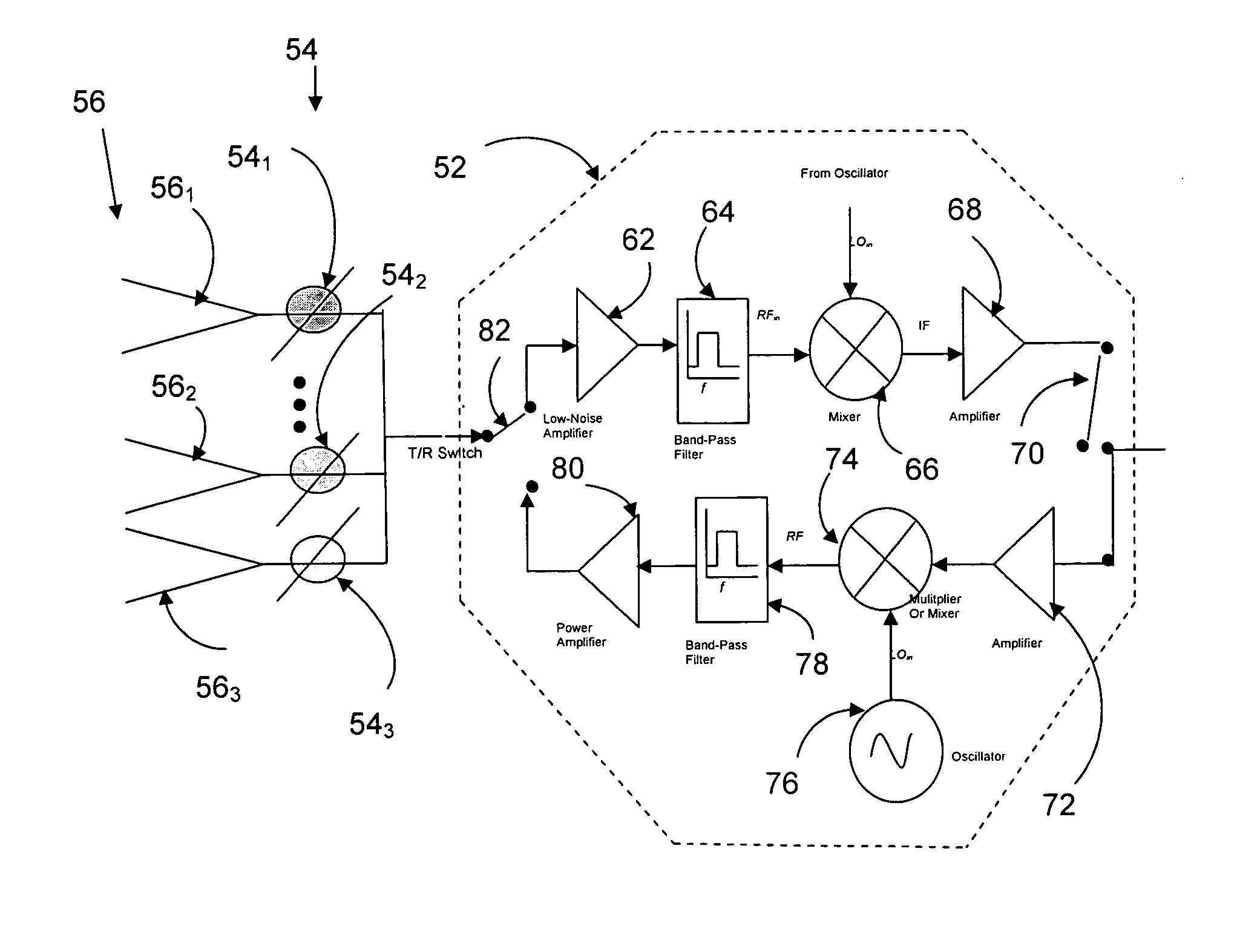
[0027] In FIG. 7, the components of the transmit / receive module 52 include a T / R switch 82. The T / R switch 82 alternatively connects the row 54 of phase elements to low noise amplifier 62 during receive mode or to power amplifier 80 during transmit mode. Low-noise amplifier 62 connects to band-pass filter 64 that connects to a mixer 66. Mixer 66 mixes the received signal with a current received from an oscillator with the mixed signal proceeding to amp...


PUM


Abstract

A communication module is provided with a Transmit/Receive (T/R) element fabricated from psuedomorphic HEMT, High Electron Mobility Transistor technology (PHEMT). The T/R element drives multiple Radio Frequency MEMS switch-based phasing elements. Each of the phasing elements connects to a corresponding radiation element. A large quantity of the communication elements can be placed on a single substrate chip so as to provide for a reliable and cost effective device.

Description

DEDICATORY CLAUSE [0001] The invention described herein may be manufactured, used and licensed by or for the U.S. Government for governmental purposes without payment of any royalties thereon.BACKGROUND OF THE INVENTION [0002] I. Field of the Invention [0003] The present invention pertains to drivers for radiating elements and electronically steerable arrays. [0004] More particularly the present invention pertains to a communication device having a Transmit / Receive (T / R) element fabricated from HEMT (High Electron Mobility Transistor) technology, that advantageously drives multiple radiating elements. [0005] II. Discussion of the Background [0006] Historically, electronically steerable phased arrays have utilized two types of designs. [0007] With reference to FIG. 1, the passive Electronically Steerable Array (ESA) 14 has a transmitter / receiver 18 for driving a plurality of arrayed phase shifters 16 that are connected to a radiating element or elements 10. The array 14 is passive in...

Claims


Application Information

Patent Timeline
IPC IPC(8): H01Q3/26
CPCH01Q3/26H01Q3/30H01Q21/0025
Inventor ROCK, JANICE C.
Owner UNITED STATES OF AMERICA THE AS REPRESENTED BY THE SEC OF THE ARMY
Why Eureka
Eureka Blog
Learn More