Illumination device, image reading device, and image forming apparatus

a technology of image forming apparatus and reading device, which is applied in the direction of lighting and heating apparatus, printing, instruments, etc., can solve the problems of inability to use as a light source, insufficient light intensity distribution on the surface of documents across the scanning width, and inability to uniformly and sufficiently distribute ligh

Active Publication Date: 2006-09-07
RICOH KK
View PDF7 Cites 16 Cited by
  • Summary
  • Abstract
  • Description
  • Claims
  • Application Information

AI Technical Summary

Benefits of technology

[0012] It is an object of the present invention to at l

Problems solved by technology

However, the LED, when used alone, has demerits like degradation of light intensity, rippling (unevenness of light intensity) in the main scanning direction, etc., and therefore cannot be used as a light source as it is.
In other words, as a narrow-directivity LED is used as the light source for scanning an image the LED, a peak occurs in the light distribution pattern as shown in FIG. 12, and the light intensity distribution on the surface of the document across the scanning width

Method used


Image

  • Illumination device, image reading device, and image forming apparatus
  • Illumination device, image reading device, and image forming apparatus
  • Illumination device, image reading device, and image forming apparatus

Examples


Embodiment Construction

[0030] Exemplary embodiments of the present invention are explained next with reference to the accompanying drawings.

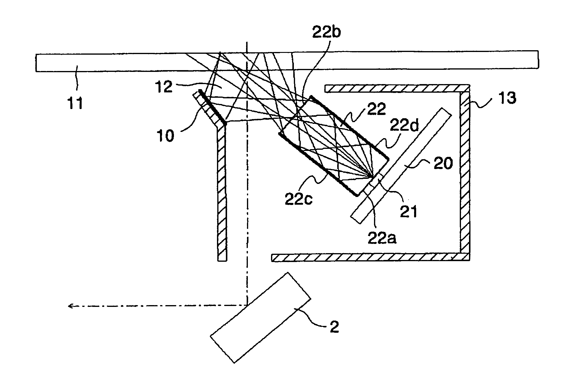
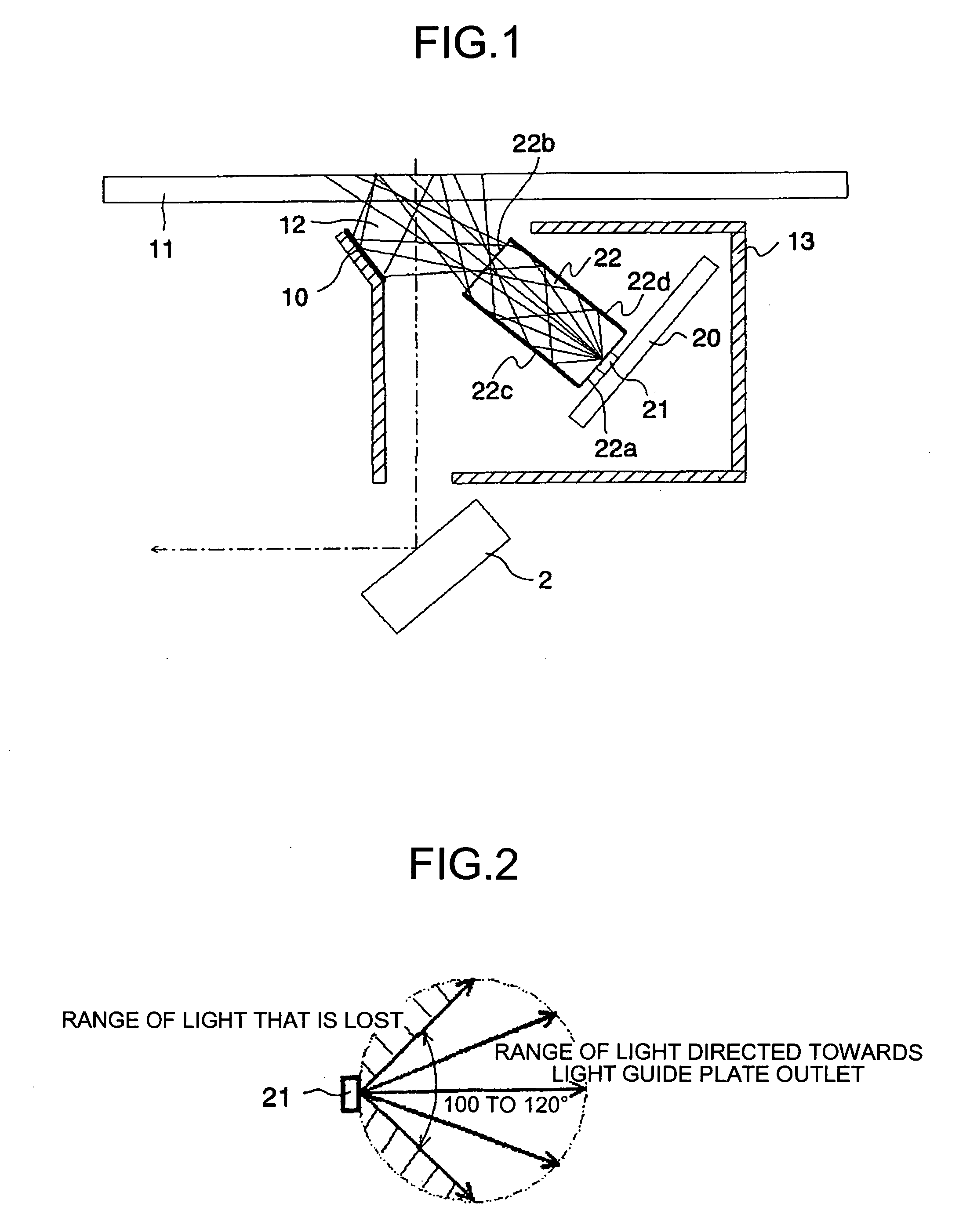
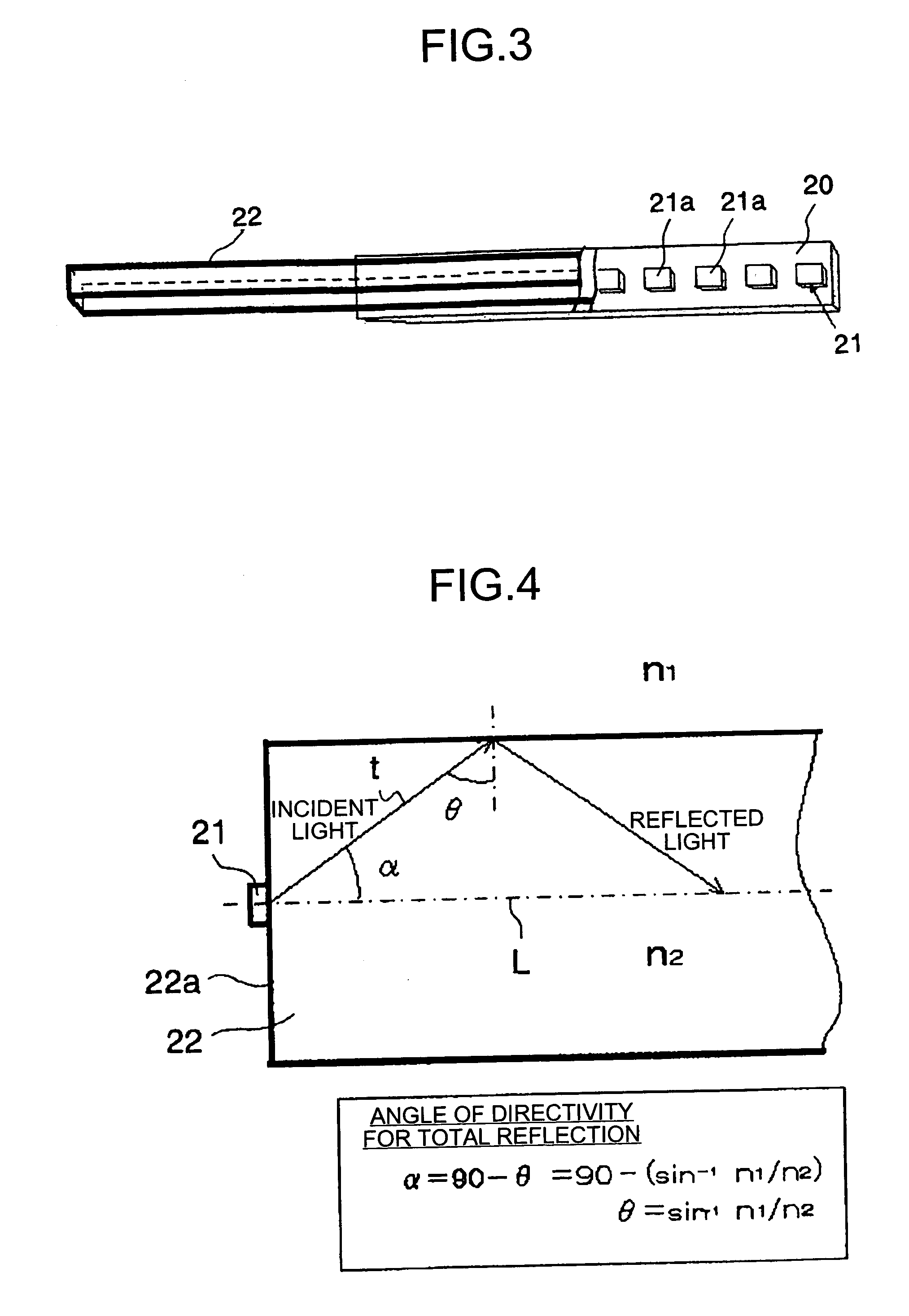
[0031]FIG. 1 is a perspective of the illumination device according to an embodiment of the present invention. The illumination device includes an LED 21 and a light guide 22. The LED 21 is a wide-directivity type light source. The LED 21 is mounted on a board 20. A first end surface (entrance surface) 22a of the light guide 22 is in contact with the LED 21, and a second end surface (exit surface) 22b points towards the direction of the light (towards the light-receiving surface). The rest of the parts are identical to those shown in FIG. 9 and have been assigned the same reference numerals.

[0032]FIG. 2 is a schematic for explaining an emission distribution of the LED 21, which is of the wide-directivity type. The range of light emitted from the emission surface of the LED 21 is 100 degrees to 120 degrees, as shown in FIG. 2. FIG. 1 is a cross-sectional drawing illus...


PUM


Abstract

An illumination device that illuminates an original document by propagating an illuminating light beam output from each of a plurality of light emitting diodes from a first end surface of a light guide to a second end surface of the light guide. Assuming that A is a dimension from the first end surface of the light guide to the second end surface of the light guide, B is an interval between adjoining light emitting diodes, the light emitting diodes being arranged in an array format in a main scanning direction, n1 is a refractive index of atmosphere outside of the light guide, and n2 is a refractive index of the light guide, a condition of tan−1(B/2A)≦β≦π/2−{sin−1(n1/n2)} is satisfied.

Description

CROSS-REFERENCE TO RELATED APPLICATIONS [0001] The present document incorporates by reference the entire contents of Japanese priority document, 2005-057541 filed in Japan on Mar. 2, 2005. BACKGROUND OF THE INVENTION [0002] 1. Field of the Invention [0003] The present invention relates to an illumination device that employs light emitting diodes (LEDs), an image reading device that reads images of an original document by illuminating the original document with the illumination device, and an image forming apparatus incorporating the image reading device and equipped with copying capabilities such as monochromatic copying, full color copying, multi function capabilities, etc. [0004] 2. Description of the Related Art [0005]FIG. 9 is a schematic diagram of a conventional image reading device (hereinafter, “scanner”) that scans images of an original document. A scanner 200 basically includes a document plate (contact glass plate) 11 on which the original document is placed, a first carr...

Claims


Application Information

Patent Timeline
IPC IPC(8): G03G15/01G03B27/54H04N1/04
CPCG02B6/0008H04N1/02835Y10S362/80
Inventor SAKURAI, YASUO
Owner RICOH KK
Why Eureka
Try Eureka