Image-taking apparatus

Inactive Publication Date: 2006-09-07
FUJIFILM CORP
View PDF8 Cites 11 Cited by
  • Summary
  • Abstract
  • Description
  • Claims
  • Application Information

AI Technical Summary

Benefits of technology

[0025] As a result, it is possible to define the first time interval synchronously with any of these cycles. In this way, it is possible to perform the process at a higher speed.
[0026] Accord

Problems solved by technology

Here, in the case of image taking with an image-taking apparatus including the dimming function of the preliminary light emission type, overexposure, underexposure, or the like may occur because the amount of light emission at the time of main light emissi

Method used


Image

  • Image-taking apparatus
  • Image-taking apparatus
  • Image-taking apparatus

Examples


first embodiment

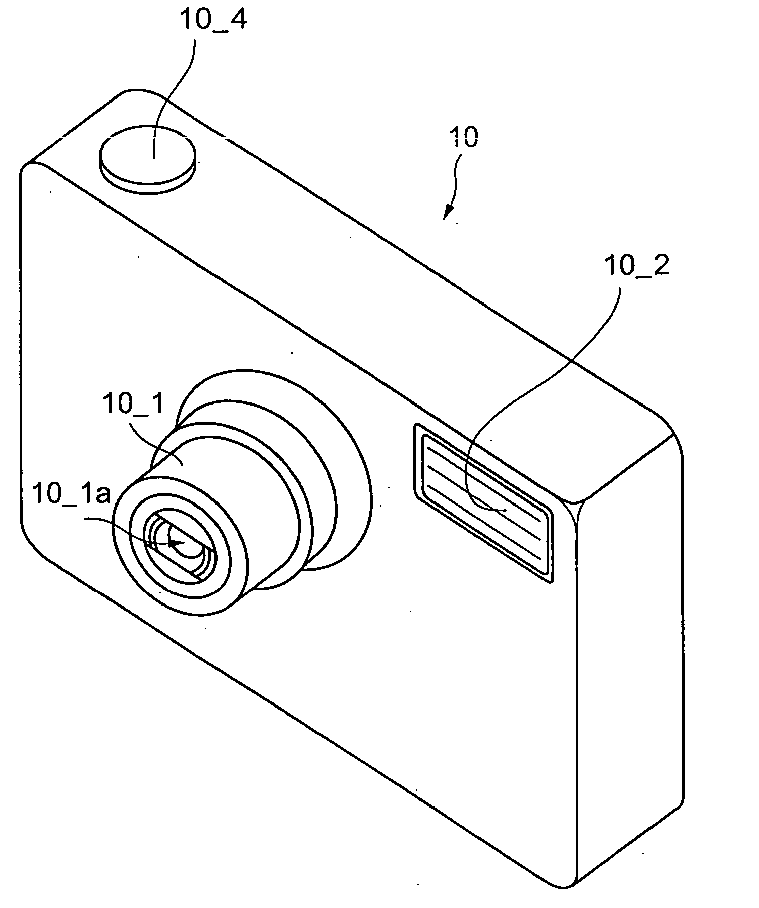
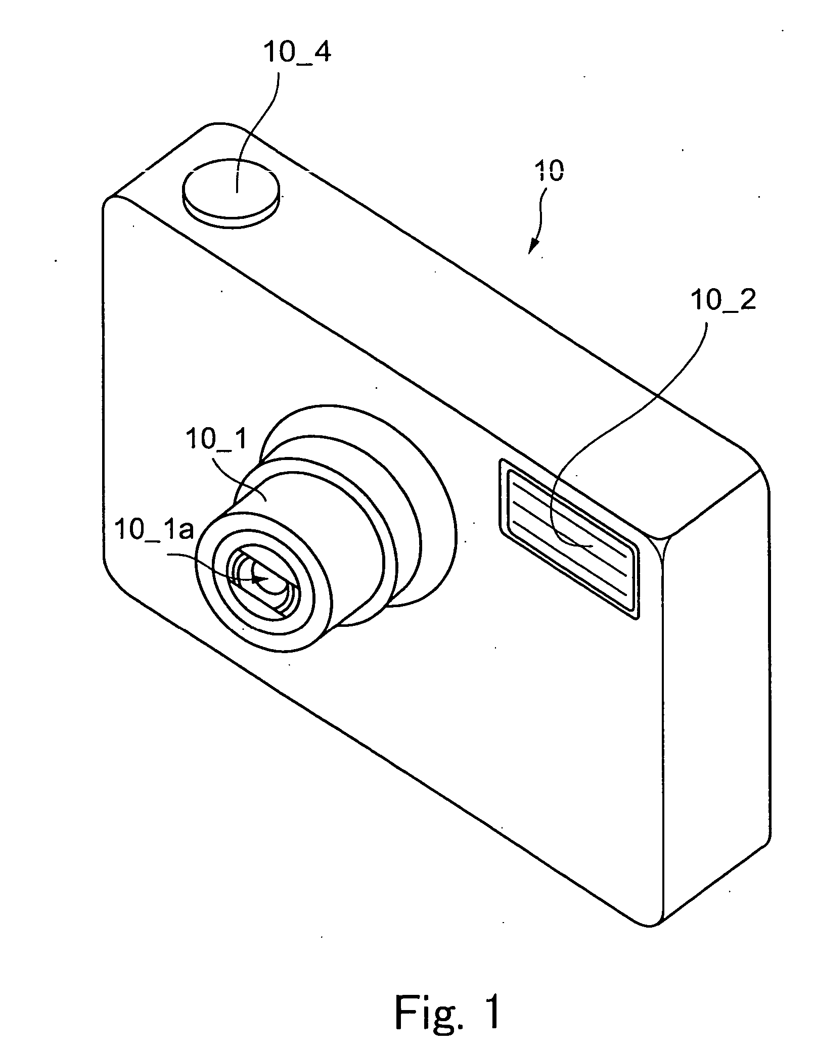
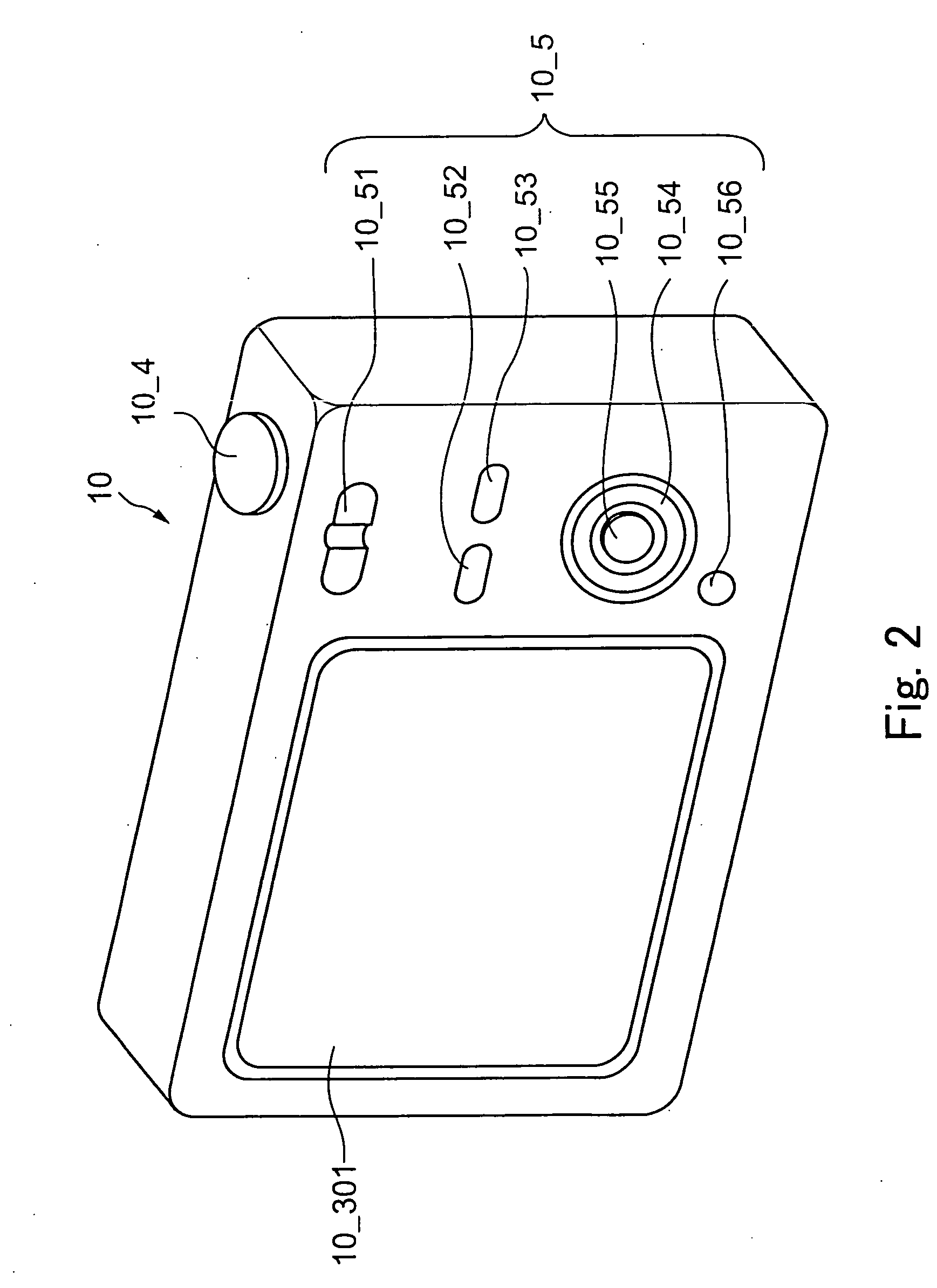
[0035]FIG. 1 and FIG. 2 are perspective views of a digital camera representing the present invention, which illustrate front and back faces viewed from obliquely above, respectively.

[0036] A lens barrel 10_1 is disposed on the front face of a digital camera 10 shown in FIG. 1 in a stretched state so as to protrude from a body. This lens barrel 10_1 has the stretched mode as shown in FIG. 1, and a folded mode in which the lens barrel 10_1 is housed inside the body by reducing a barrel length as compared to the barrel length in the stretched mode.

[0037] Meanwhile, an image-taking lens 10_1a formed of a focal length variable zoom lens is disposed inside this lens barrel 10_1. Moreover, a flash firing window 10_2 for emitting flash light at the time of image taking is disposed on the front face of this digital camera 10. In addition, a shutter release button 10_4 for giving an image-taking instruction to the camera is arranged on an upper face of the body of the digital camera 10.

[003...

second embodiment

[0082]FIG. 6 is a flowchart performed by a digital camera according to the present invention.

[0083] The digital camera according to the second embodiment has an appearance similar to FIGS. 1 and 2 and an internal configuration similar to FIG. 3. However, contents of a program described in an internal memory 10_471 of the CPU 10_47 are different from those shown in FIG. 3. The same components of the second embodiment as those of the first embodiment are denoted with the same reference characters in the following description.

[0084] Now, the different procedures will be described with reference to FIG. 6.

[0085] In FIG. 5, the process is performed by use of the cycle (50 ms) so as to eliminate the influence of the flicker light source irrespective of whether the intensity variation of the flicker light source is synchronized with the commercial power source having the frequency of 50 Hz or the commercial power source having the frequency of 60 Hz.

[0086] On the other hand, in the seco...


PUM


Abstract

An image-taking apparatus performs a correct dimming process while eliminating an influence of flickers in the case of image taking by use of flash light under a flicker light source that exhibits intensity variation of illumination light at a commercial power source frequency of 50 Hz or 60 Hz. A time period of 50 milliseconds is defined as a process cycle as zero points coincide with each other between those of the two frequencies. An amount of light received from an object field is obtained in a first 50-millisecond interval after a full-press action, and an amount of preliminary light emission is obtained in a second 50-millisecond interval. An appropriate amount of light for main light emission is obtained in a third 50-millisecond interval. In this way, main light emission is performed at an accurate amount of light emission.

Description

BACKGROUND OF THE INVENTION [0001] 1. Field of the Invention [0002] The present invention relates to an image-taking apparatus configured to perform image taking by use of flash firing depending on an image-taking operation. [0003] 2. Description of the Related Art [0004] There are many image-taking apparatuses including a flash firing device for performing flash firing depending on an image-taking operation. Some of those image-taking apparatuses include a dimming function to control an amount of light emission of flash light into an appropriate value. Such a dimming function is roughly categorized into a type configured to perform preliminary light emission in preparation to main light emission and thereby to calculate an amount of light emission at the time of the main light emission (hereinafter referred to as a “preliminary light emission type”), and a type configured to receive reflection of flash light reflected by an object field using a dimmer sensor and to stop emission of...

Claims


Application Information

Patent Timeline
IPC IPC(8): H04N9/73G03B7/16G03B15/00G03B15/05H04N5/238H04N101/00
CPCH04N5/2354H04N5/2357H04N23/745H04N23/74
Inventor NOSE, SYUJI
Owner FUJIFILM CORP
Why Eureka
Try Eureka