
Portable work light

a work light and portable technology, applied in the field of portable work lights, can solve the problems of heavy damage to work lights, heavy impact on work lights, and high temperature changes, and achieve the effect of simplifying assembly or replacement of modular components

Inactive Publication Date: 2006-09-07
CPS PROD CANADA
View PDF8 Cites 34 Cited by
  • Summary
  • Abstract
  • Description
  • Claims
  • Application Information

AI Technical Summary

Benefits of technology

[0007] A work light having a tray, which can be compartmentalized, for holding light components including a light source, power source and electrical control unit is disclosed. The components can easily be assembled on the tray for operation of the light. The tray can include barriers into which modular components of the light can fit. The barriers simplify assembly or replacement of the modular components and protects the components by limiting their movement with respect to each other. In an embodiment, the tray contains an electronic control unit compartment which can hold an electronic control unit. The tray can contain a battery compartment which can hold a battery powered power source. The tray can also contain a light source compartment that can hold a light source. The tray is held by a housing or casing containing a light transmissible portion which surrounds it. A cap having a hollow shell body with an opening at one end can be used to close the end of the housing. In an embodiment the cap can have a rotatable hook, which extends away from the work light, that can be used to suspend the work light in a work environment.

Problems solved by technology

Service technicians are often required to perform repair services in areas that are difficult to access and are poorly lit.
Because work lights are employed in many different work environments, such as vehicle repair, maintenance work, construction and the like; the lights are subject to impacts, shocks, falls, drops, harsh chemicals, and large temperature changes from below freezing to significant heat, such as from a motor vehicle engine.
As a consequence, work lights often suffer damage.
Some damage can be severe and may cause the light to cease functioning.
Work light repair can be a lengthy procedure requiring delivery of the non-functioning light to a repair facility, repair and then return of the work light to its owner.
This is an inefficient and time-consuming process.

Method used


Image

  • Portable work light
  • Portable work light
  • Portable work light

Examples


Embodiment Construction

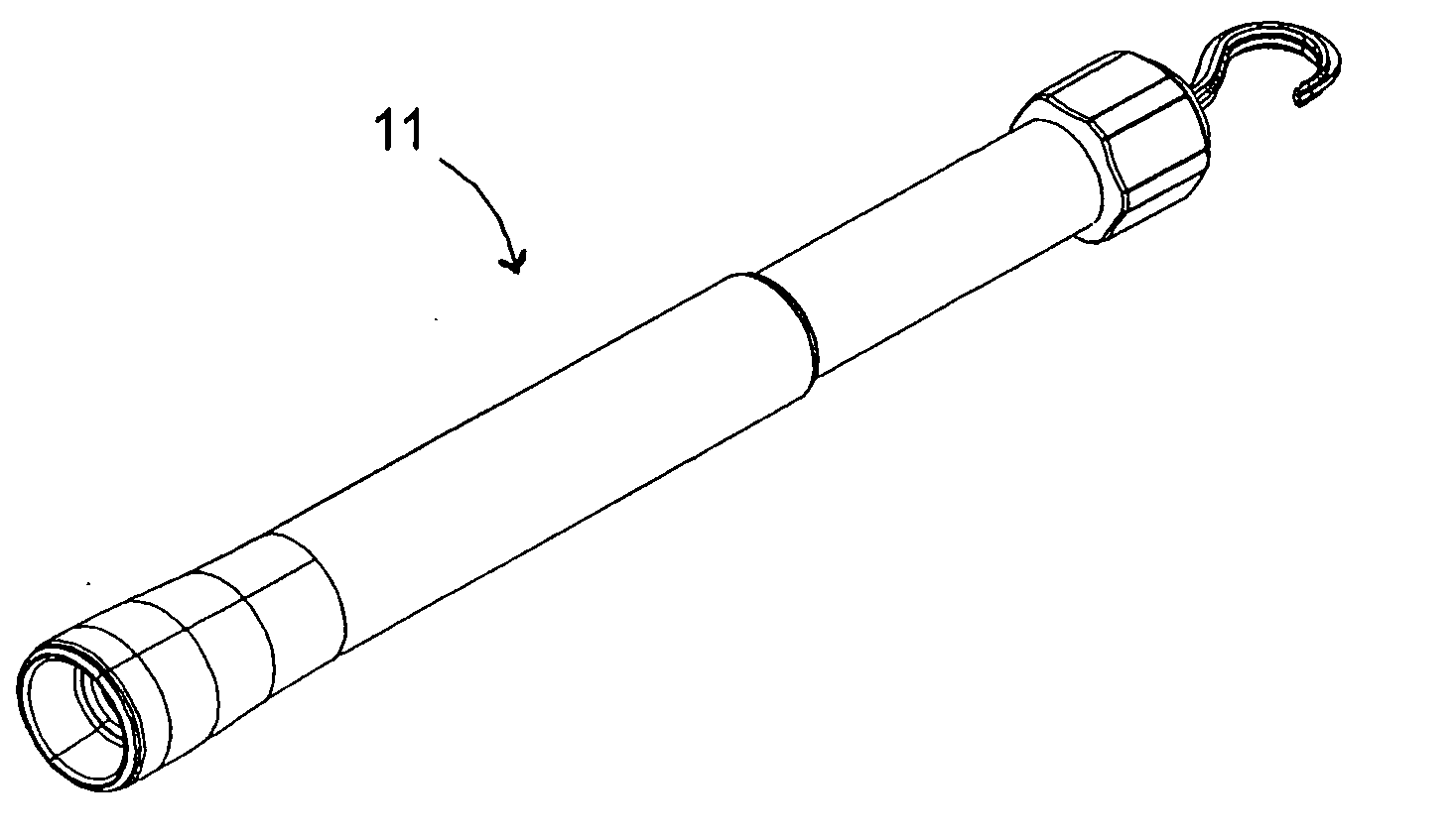
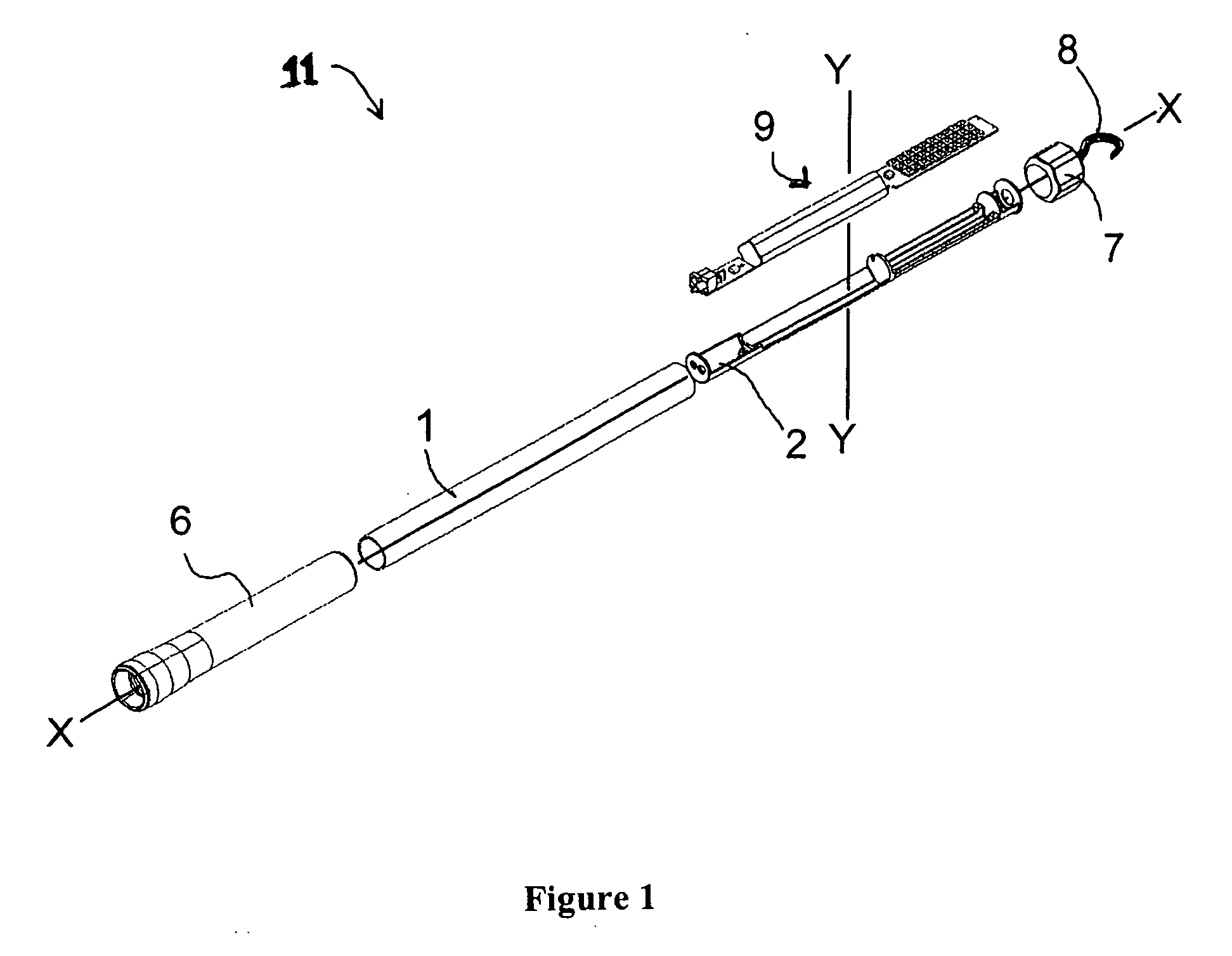
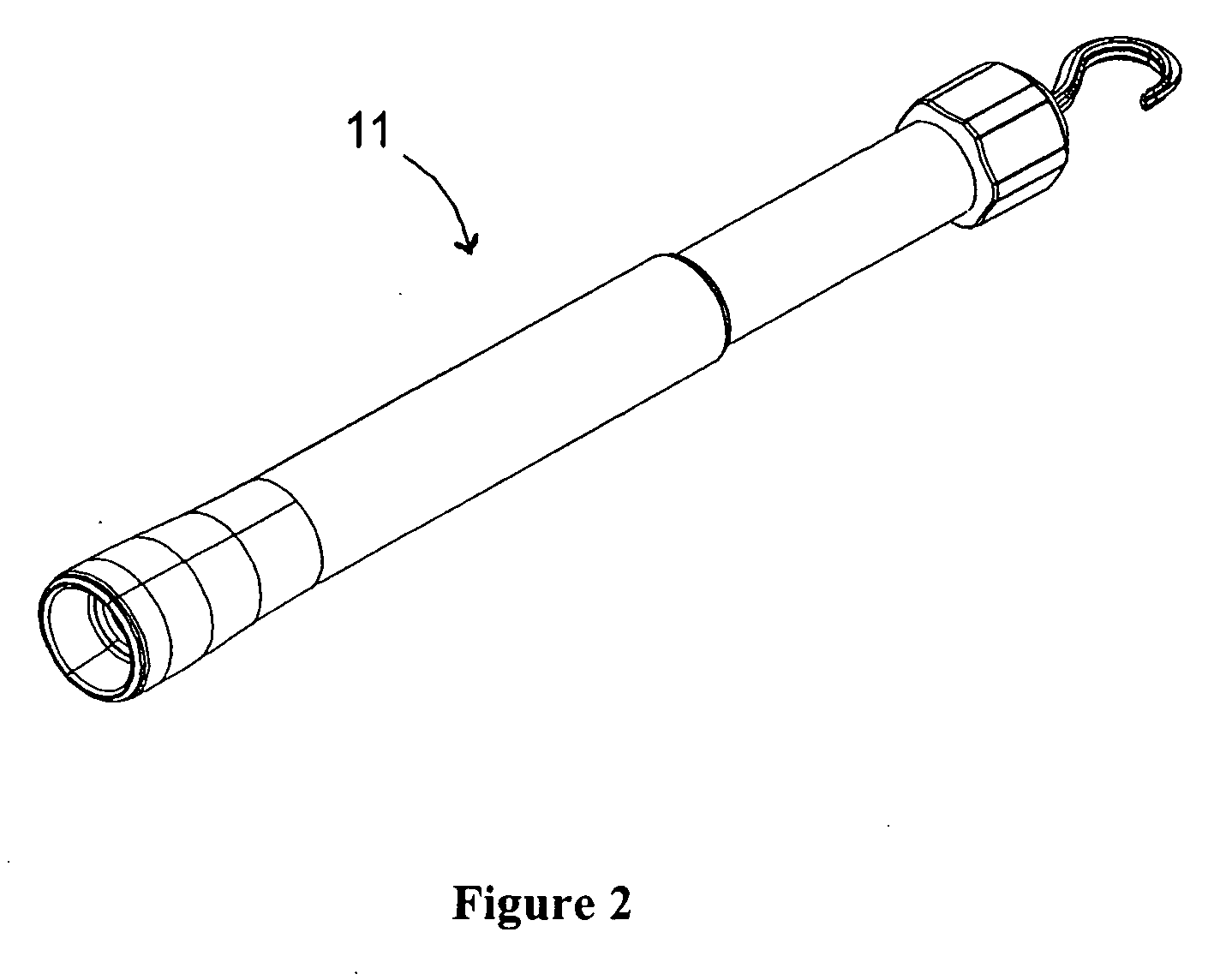
[0020] Referring to FIGS. 1 and 2, the present invention will be seen to relate to a highly serviceable, portable work light 11. As illustrated, the invention provides a light source operably connected to components that include a power source and an electronic control mechanism. In an embodiment, the components of the device can be assembled on a support tray 2 which can be inserted in an extended hollow body or housing 1. Internal components 9 of work light 11, including a power source 3, a light source 4 and an electronic control mechanism 5 can be located on support tray 2. The components can be adapted such that they fit into compartments in the tray in a unique manner such that they can be conveniently replaced.

[0021] The hollow body 1 of work light 11 has a transparent, light transmissible portion and can have an opening at one or both ends, as illustrated in FIG. 1. Body 1 is preferably made of a resilient plastic material. The body can have a light-transmissive portion and...


PUM


Abstract

The present specification discloses a work light having a tray for holding or positioning light components such as a light source, power source and electrical control unit. The components can easily be assembled on the tray for operation of the light. The tray can be compartmentalized by including barriers into which the modular components of the light fit. Such barriers provide for very simple assembly or replacement of the components and protect the components by limiting their movement with respect to each other. In an embodiment the tray contains a compartment for holding an electronic control unit. The tray can contain a battery compartment which can hold a battery powered power source. The tray can also contain a light source compartment for holding a light source. The tray can be supported by a housing or casing containing a light transmissible portion which surrounds at least a portion of the tray. A cap having a hollow shell body with an opening at one end can be used to close the end of the housing. In an embodiment the cap can have a rotatable hook, which extends away from the work light, that can be used to suspend the work light in a work environment.

Description

CROSS REFERENCE TO RELATED APPLICATIONS [0001] This application claims priority to U.S. Provisional Application No. 60 / 659,746 filed on Mar. 7, 2005.BACKGROUND OF THE INVENTION [0002] Service technicians are often required to perform repair services in areas that are difficult to access and are poorly lit. They commonly employ work lights to provide additional illumination in these areas. The work light can be placed in a variety of positions in a work area to direct a sufficient amount of additional light into a work space, as needed. Such lights need to be relatively compact and portable, yet they must be able to provide light in sufficient quantity, with a large enough beam to be concentrated upon the part or element being repaired. [0003] These devices are well known by such names as work lights, trouble lights, utility lights, inspection lights and the like. [0004] Because work lights are employed in many different work environments, such as vehicle repair, maintenance work, co...

Claims


Application Information

Patent Timeline
Patent Type & Authority Applications(United States)
IPC IPC(8): F21L4/08F21L4/04
CPCF21L4/027F21L4/085F21Y2101/02F21Y2115/10
Inventor TRIGIANI, PHILFERRARO, TONYCOULSON, RICHARD ROBERT
Owner CPS PROD CANADA
Learn More