
Apparatus and method for tracking a sampling clock of multi-carrier communication system

a communication system and multi-carrier technology, applied in the field of communication systems, can solve the problems of inter-carrier interference (ici), computation process, and large consumption of resources during the process

Active Publication Date: 2006-09-07
REALTEK SEMICON CORP
View PDF3 Cites 1 Cited by
  • Summary
  • Abstract
  • Description
  • Claims
  • Application Information

AI Technical Summary

Benefits of technology

The invention provides a way to track the sampling clock of a multi-carrier communication system. This is done by generating two sets of data removal symbols, and then using those symbols to create a control signal to compensate for any sampling clock issues. The technical effect of this invention is to improve the accuracy and reliability of multi-carrier communication systems.

Problems solved by technology

This phase shift may cause inter-carrier interference (ICI) regarding the received symbol.
Unfortunately, a great deal of resources is consumed during the above-mentioned computation processes.

Method used


Image

  • Apparatus and method for tracking a sampling clock of multi-carrier communication system
  • Apparatus and method for tracking a sampling clock of multi-carrier communication system
  • Apparatus and method for tracking a sampling clock of multi-carrier communication system

Examples


Embodiment Construction

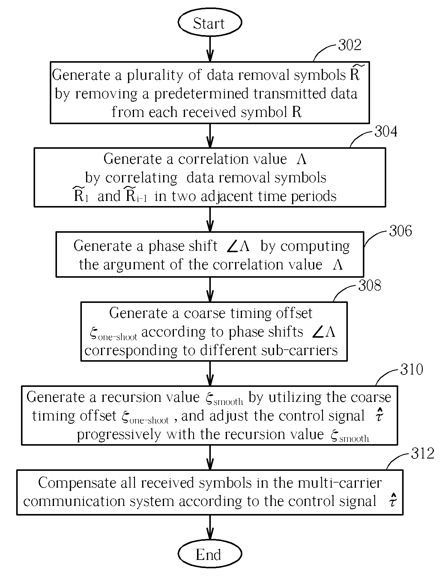
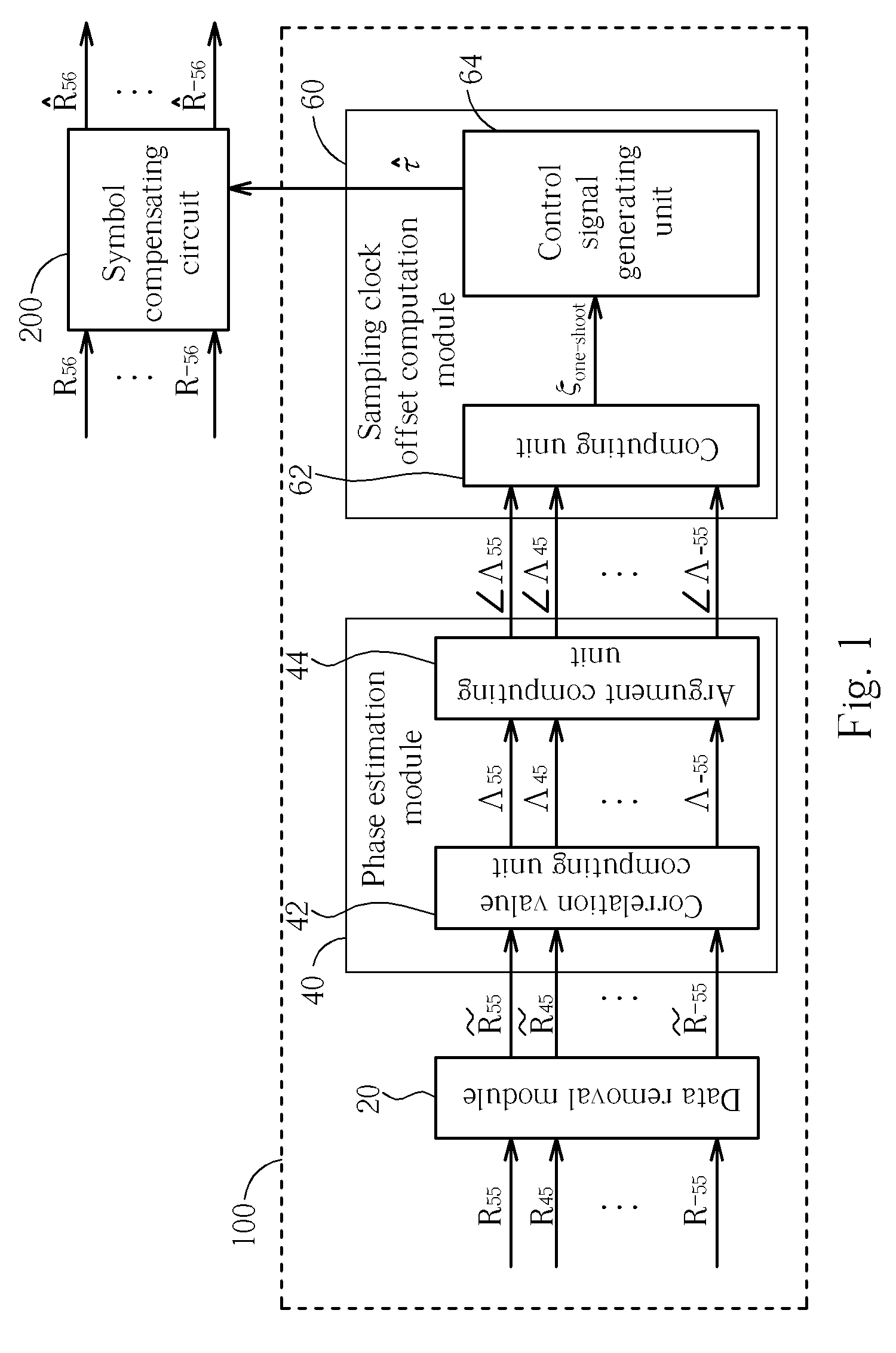
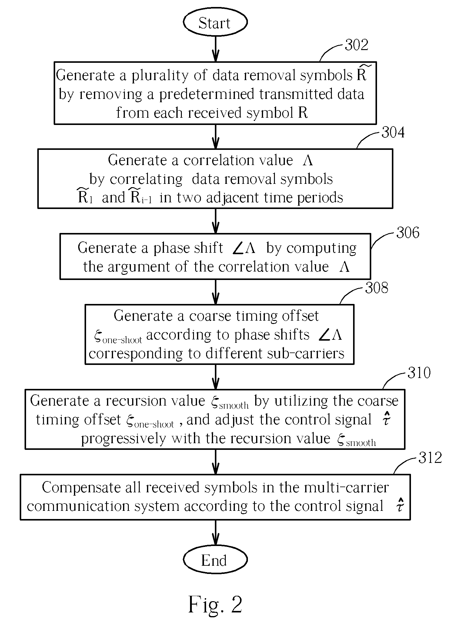
[0014] Please refer to FIG. 1. FIG. 1 is a diagram of a sampling clock tracking apparatus 100 according to an embodiment of the present invention. The sampling clock tracking apparatus 100 is applied in a multi-carrier communication system for estimating a preliminary sampling clock offset ζone-shoot according to a number of received symbols R55, R45, . . . , R−55 with corresponding pilot symbols, and generating a control signal {circumflex over (τ)} according to the preliminary sampling clock offset ζone-shoot, and then transmitting the control signal {circumflex over (τ)} to a symbol compensating circuit 200 of the multi-carrier communication system to compensate all received symbols R56, . . . , R−56 (which include data symbols and pilot symbols) in the multi-carrier communication system, to generate received symbols {circumflex over (R)}56, . . . , {circumflex over (R)}−56, which are not influenced by sampling clock offsets. As shown in FIG. 1 the sampling clock tracking apparat...


PUM


Abstract

An apparatus and a method for tracking a sampling clock of a multi-carrier communication system are disclosed, the apparatus including a data removal module, a phase estimation module, and a sampling clock offset computation module. The data removal module is for generating a plurality of first and second data removal symbols by removing predetermined transmitted data from a plurality of first and second received symbols, respectively. The phase estimation module for generating a first and a second phase shifts according to correlations of the plurality of first and second data removal symbols. The sampling clock offset computation module for generating a control signal utilized to compensate the sampling clock of a plurality of received symbols according to the first and a second phase shifts.

Description

BACKGROUND OF THE INVENTION [0001] 1. Field of the Invention [0002] The present invention relates to a communication system, and more specifically, to an apparatus and a related method for tracking a sampling clock of a multi-carrier communication system. [0003] 2. Description of the Prior Art [0004] As is well known in the art, a multi-carrier communication system utilizes a plurality of sub-carriers to modulate predetermined transmitted data, then proceeds to transmit the modulated data to a receiver in the form of a continuous data flow. At this time, the receiver samples the above-mentioned continuous data flow utilizing a sampling clock. A phase shift may exist between the received symbol generated by the receiver and the original transmitted data transmitted by the transmitter. This is apparent when the frequency of the sampling clock shifts by a small offset. This phase shift may cause inter-carrier interference (ICI) regarding the received symbol. [0005] A multi-carrier comm...

Claims


Application Information

Patent Timeline
Patent Type & Authority Applications(United States)
IPC IPC(8): H04L7/00H04K1/10
CPCH04L27/2662H04L27/2675
Inventor WU, KUO-MING
Owner REALTEK SEMICON CORP
Learn More