Vent assembly

a technology of vent assembly and vent fitting, which is applied in the direction of valve construction, lighting and heating apparatus, heating types, etc., can solve the problems of deformation of the visible surface of the plated surface the relatively complex form of the vent fitting, and the deformation of the appearance of the plated fitting

Inactive Publication Date: 2006-09-07
ITC LIMITED
View PDF5 Cites 83 Cited by
  • Summary
  • Abstract
  • Description
  • Claims
  • Application Information

AI Technical Summary

Benefits of technology

[0007] This invention relates to a vent assembly, suitable for marine uses including, for example, venting an enclosure, such as an engine compartment, on a boat, whic

Problems solved by technology

To accomplish its various purposes, such vent fitting is of relatively complex form.
However, the present assignee has found that for more expensive lines of boats, boat manufacturers and their buyers prefer more expensive looking fittings, e.g. stainless steel fittings, rather than less expensive looking molded plastics fittings.
While generally successful commercially, the present assignee has found that continuing contact, over a long period of time, with the elements in a harsh salt water marine environment,

Method used


Image

  • Vent assembly
  • Vent assembly
  • Vent assembly

Examples


Embodiment Construction

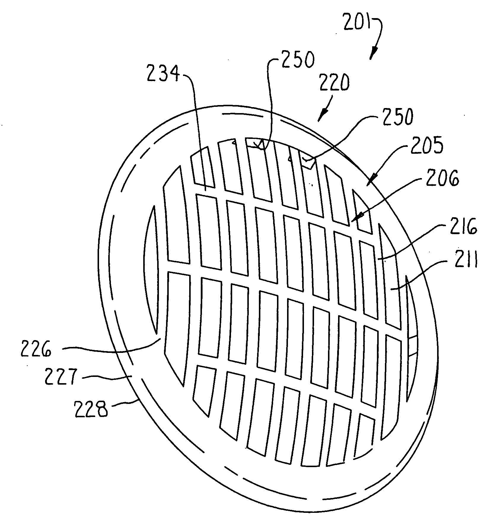
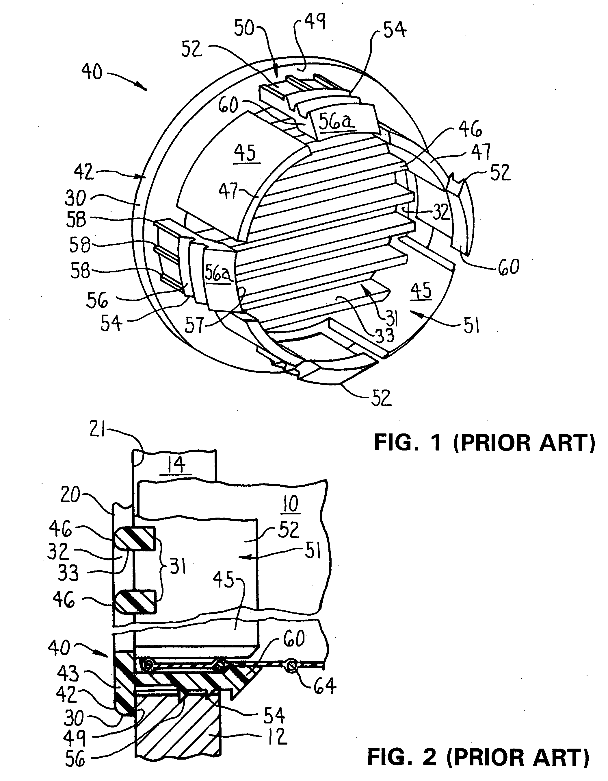
[0021] A vent 40 (FIGS. 1 and 2) is here formed to function as a hose fitting. The vent 40 is formed (preferably molded) of a suitable substantially rigid molded plastics material, such as nylon or polypropylene. The molded plastics vent 40 includes a radially extending head 42, here in the form of a circular face plate. The head 42 has a radially outward facing edge 30 and a continuous peripheral edge portion 43 inboard of the edge 30. The head 42 is perforated by a pattern of elongate ventilating slots 31 extending axially therethrough and laterally to the peripheral edge portion 43. The slots 31 have end walls 32 at the peripheral edge portion 43. The slots are separated by flanking straps 46 defining side walls 33 of the slots 31. The head 42 has front and back sides 20 and 21 respectively separated by the radially outward facing edge 30 and to which the slots 31 open.

[0022] The molded plastics vent 40 also has a generally tubular base 50 extending substantially coaxially from ...


PUM


Abstract

A vent assembly, suitable for marine use including, for example, venting an enclosure, such as an engine compartment, on a boat. The vent assembly has substantially the external appearance of a cast or machined, one piece, stainless steel vent, at a cost very little more than a molded plastics vent. A molded plastics vent has a head perforated by a pattern of ventilating slots separated by flanking strips. A decorative, corrosion-resistant, sheet metal cover shell lies tight against the front side of the molded plastics vent and has a pattern of slots and strips mapping substantially on the pattern of slots and strips of the molded plastics vent. Snap-fit fasteners fix the cover shell on the vent so that the cover shell slots are a substantially flush continuation of the vent slots, so as to provide the decorative appearance of a solid metal vent at substantially lower cost and without compromising or through flow capability.

Description

FIELD OF THE INVENTION [0001] This invention relates to slotted vents, and more particularly to slotted vents usable in marine applications such as for ventilating a motor enclosure on a boat. BACKGROUND OF THE INVENTION [0002] U.S. Pat. No. 5,588,908, assigned to the assignee of the present invention, discloses a apparatus for fixing a ventilating hose at an opening in a wall of an enclosure, e.g. for use on a boat in venting gases from the engine compartment, or venting cooking odor laden air from the galley, or admitting air. That apparatus includes a vent fitting comprising a radially extended, slotted head adapted to rest against the exterior face of the wall to hide an opening therein and a tubular body extending from the rear face of the head through the wall opening, to fix the vent fitting and an attached, rearwardly extending hose to the wall at the opening, to communicate flow through the hose and slotted head. To accomplish its various purposes, such vent fitting is of r...

Claims


Application Information

Patent Timeline
IPC IPC(8): B63B19/04
CPCB63B2231/06B63J2/10F24F13/084
Inventor HARTMANN, RICHARD JR.CAMAROTA, RICHARD J.
Owner ITC LIMITED
Why Eureka
Try Eureka