
Vehicle structural components made from tubular members and method therefor

a technology of tubular components and structural components, which is applied in the direction of vehicle springs, understructures, interconnection systems, etc., can solve the problems of weak spots in the formed product, insufficient method, and large addition of processing tim

Inactive Publication Date: 2006-09-14
ARCELORMITTAL TUBULAR PRODS CANADA
View PDF18 Cites 57 Cited by
  • Summary
  • Abstract
  • Description
  • Claims
  • Application Information

AI Technical Summary

Benefits of technology

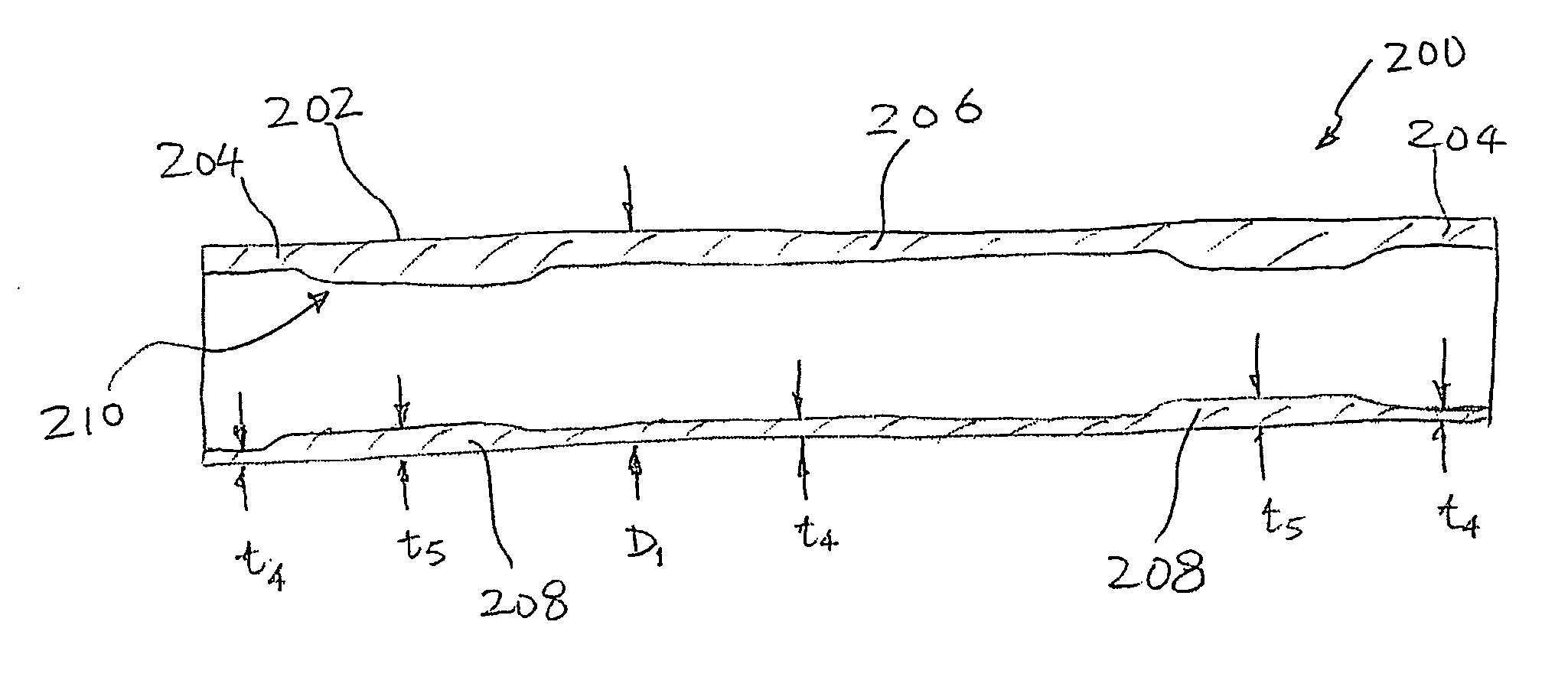
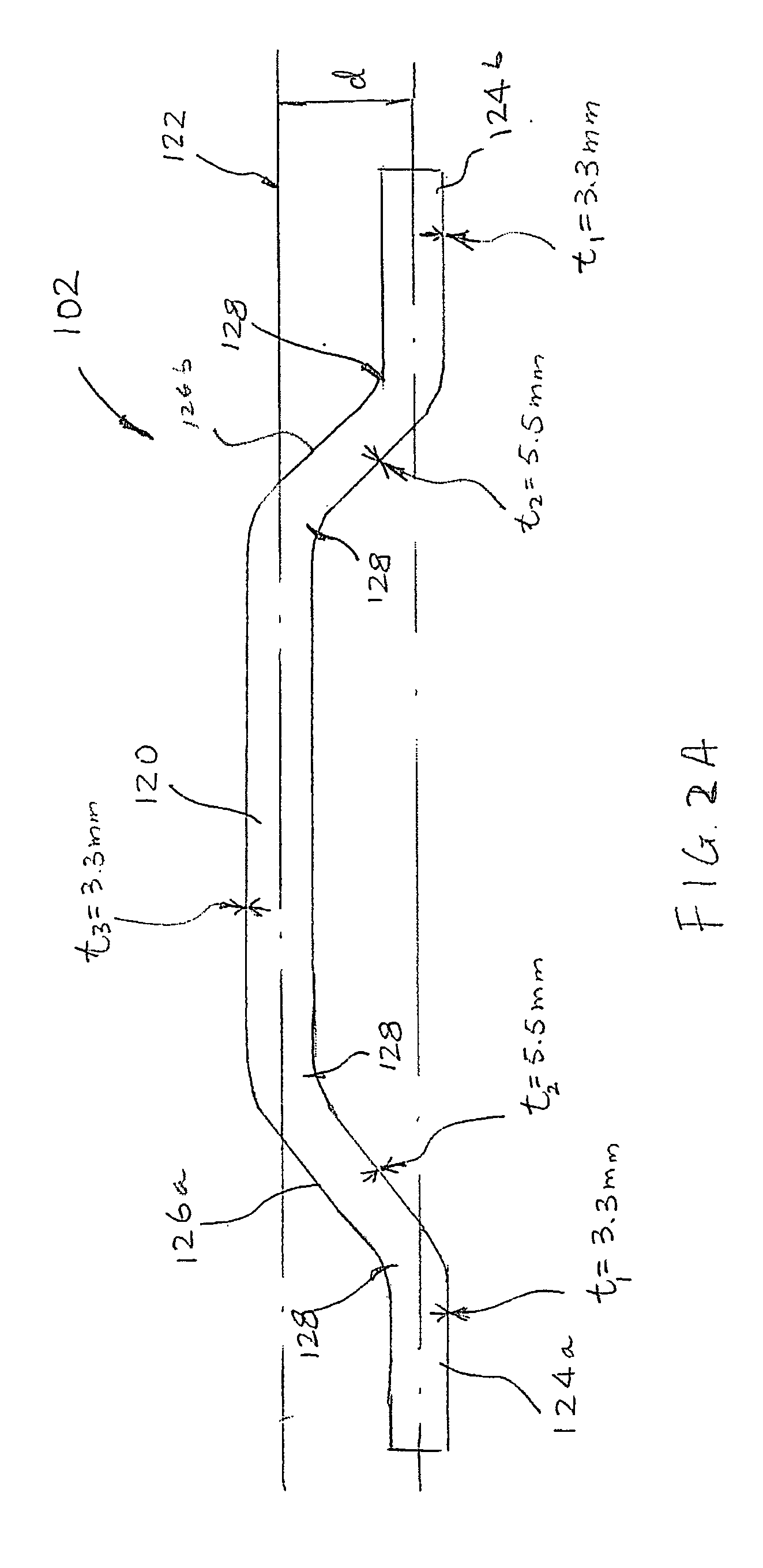
[0006] In a first aspect of the invention, there is provided a cross member for a rear suspension assembly. The cross member comprises a unitary tubular member, the tubular member having a variable wall thickness along its length. The tubular member has a generally elongated center portion, a pair of end portions and a pair of intermediate sections each formed between the center portion and one of the end portions. The pair of intermediate sections integrally connecting the end portions to the center portion. The center portion defines a longitudinal axis along the center portion and each of the end portions is displaced from and generally parallel with the longitudinal axis. The wall thickness at the end portions is smaller than the wall thickness at the intermediate sections.
[0007] In another aspect, there is provided an engine support structure for supporting an engine of a vehicle. The engine support structure includes a pair of side rails spaced from each other, and a front cross member and a rear cross member spaced from the front member, the front and rear cross members joining the side rails to form a general quadrilateral shape. Each of the side rails is formed from a unitary tubular member. The unitary tubular member has a variable wall thickness along its length, the wall thickness monotonically increasing along the unitary tubular member in a forward direction in a substantial portion of the unitary tubular member.

Problems solved by technology

Although resulting in the required variable wall blank, this method is not entirely satisfactory for several reasons.
Firstly, the method involves the pre-forming step of creating the blank using a welding procedure, which adds a considerable amount to the total processing time.
Secondly, the presence of welds may lead to weak spots in the formed product.
Thirdly, the sudden changes in wall thickness associated with this method also tend to introduce undesirable physical properties of the final product.
The management of impact energy and design of dynamic properties also tend to become more difficult as a result.

Method used


Image

  • Vehicle structural components made from tubular members and method therefor
  • Vehicle structural components made from tubular members and method therefor
  • Vehicle structural components made from tubular members and method therefor

Examples


Embodiment Construction

[0026] The description which follows and the embodiments described therein are provided by way of illustration of an example, or examples, of particular embodiments of the principles of the present invention. These examples are provided for the purposes of explanation, and not limitation, of those principles and of the invention. In the description which follows, like parts are marked throughout the specification and the drawings with the same respective reference numerals.

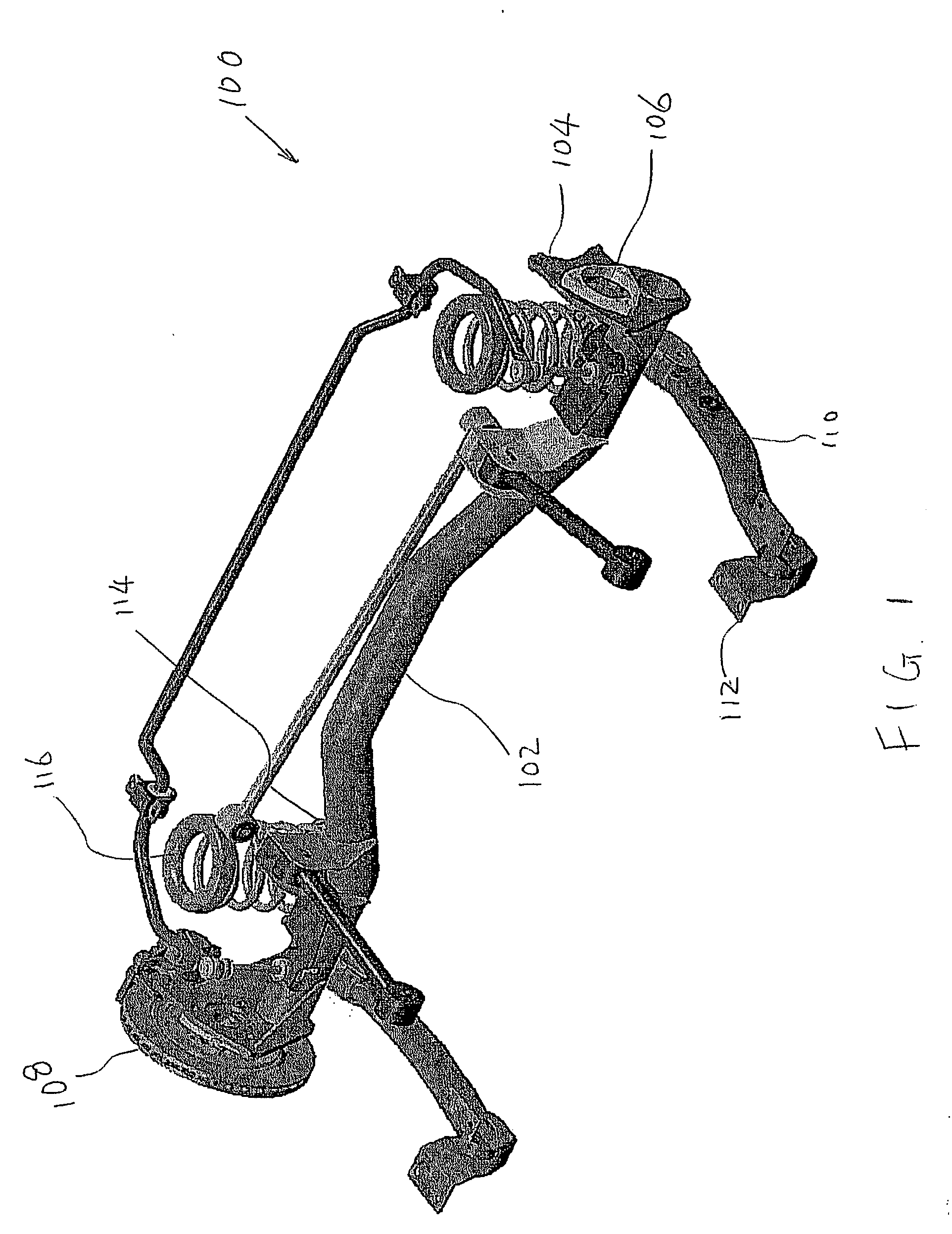
[0027]FIG. 1 shows a rear suspension assembly 100. As is well known, a rear suspension serves to connect a vehicle body to the rear road wheels. FIG. 1 shows a rear suspension for a vehicle whose rear wheels are not driven nor steerable. However, it will be understood that the invention is not limited to such rear suspensions.

[0028] As can be seen from FIG. 1, the rear suspension assembly 100 has a tubular cross member, or cross beam 102. Mounted to each end of tubular cross beam 102 is an end plate 104. End pla...


PUM

PropertyMeasurementUnit
wall thickness t2aaaaaaaaaa
thicknessaaaaaaaaaa

Abstract

The invention provides rear suspension structures and engine cradles involving tubular components. The tubular components have variable wall thickness along the length for reducing materials required. The tubular components also have mechanical properties varying along the length of the tubular components, to meet the requirements on strength and dynamic and static loads. The weight of the tubular components can be further reduced by appropriately varying the wall thickness and mechanical properties along the length of the tubular components.

Description

[0001] This application claims the benefit of U.S. Provisional Application No. 60 / 614,494 filed on Oct. 1, 2004.1. FIELD OF INVENTION [0002] The present invention relates to structural components used in vehicles and a method of forming same. 2. BACKGROUND OF INVENTION [0003] In the automotive industry, various structural components are of late made from tubular blanks. This is mainly due to the fact that tubular components can often combine strength with significant weight and material reduction. [0004] In manufacturing the above mentioned structural components, it is known to design the tubular blanks with a variable wall thickness in order to, inter alia, have localized reinforcement in regions of the components that are subject to stress. Various methods have been suggested to provide such blanks with variable wall thickness. For example, the method taught in U.S. Pat. No. 5,333,775 provides a blank comprised of tubular pieces of different wall thickness that are welded together...

Claims


Application Information

Patent Timeline
Patent Type & Authority Applications(United States)
IPC IPC(8): B21D26/02B21C37/30
CPCB21C1/24B21C37/16B21D26/033B21D53/88B21K1/12B60G21/051B60G2200/21B60G2200/42B60G2200/446B60G2202/12B60G2202/134B60G2202/136B60G2202/1362B60G2204/1226B60G2204/1246B60G2204/148B60G2204/15B60G2204/18B60G2204/43B60G2204/4302B60G2206/012B60G2206/20B60G2206/427B60G2206/50B60G2206/604B60G2206/8103B60G2206/8106B60G2206/8107B60G2206/8201B62D21/11
Inventor LEPRE, STEFANOJAHANI, MAMADNEWPORT, COLINBLAND, WAYNEVERSOLATTO, LIVIO D.
Owner ARCELORMITTAL TUBULAR PRODS CANADA
Learn More