Arrangement to increase the thermal fatigue resistance of glass tubes flowed through by fluid and pressure-loaded

a technology of glass tubes and fluids, applied in the direction of solar heat collectors with working fluids, lighting and heating apparatus, solar heat devices, etc., can solve the problems of glass tube damage, glass tube breakage, and substantial thermal fatigue resistance, so as to increase the thermal fatigue resistance of glass tube flow, the effect of low cost and low cos

Inactive Publication Date: 2006-11-21
SCHOTT AG
View PDF18 Cites 13 Cited by
  • Summary
  • Abstract
  • Description
  • Claims
  • Application Information

AI Technical Summary

Benefits of technology

[0004]It is therefore the task of the invention, to develop an arrangement to increase the thermal fatigue resistance of glass tubes flown through by fluid and pressure-loaded, which is characterized by a low expenditure for design and production, causes low costs and which does not make special demands regarding the availability of the materials to be used. The manufacturing is to take place as easily as possible and the individual glass tube should be able to be integrated into this arrangement as easily as possible.
[0006]The arrangement to increase the thermal fatigue resistance of glass tubes having fluid flowing therethrough and being pressure-loaded comprises a glass tube into which a hollow cylindrical interior component is inserted according to the invention, which has a smaller wall thickness than the glass tube and which is at least partially, preferably completely, free of a direct thermal connection with the glass tube in the condition of the glass tube being flown through by fluid. i.e. that the interior component is circulated around by fluid on two sides—at the outer circumference and at the interior circumference. The flow takes place pressure-free with a completely coaxial arrangement of the interior component to the glass tube. Between the interior of the interior component and the remaining interior of the glass tube exists a hydraulic connection, i.e. no fluid guidance separate from the fluid guidance in the gap between outer circumference of the interior component and interior circumference of the glass tube takes place in the interior of the interior component, i.e. the area circumscribed by the interior circumference. Due to the associated heat transfer between the fluid and the interior component the cooling of the inner surface of the glass tube can be delayed, so that unacceptable temperature gradients at the wall of the glass tubes are avoided. The interior component has a smaller wall thickness than the glass tube.
[0015]The solution c) is preferably used, since no special accommodations at the components glass tube or interior component are to be made and therefore standardized components and / or prefabricated components can be used, which can be combined if necessary with an additional guide device. This guide device can be connected with the glass tube interlocking and positively actuated. The guide device is preferably located positively actuated in the glass tube, for example through clamping. The guide can furthermore be connected with the interior component interlocking and / or positively actuated. In order to avoid unnecessary stresses the connection between guide device and interior component is provided with a very large fit, so that only a crude position adjustment of the interior component in relation to the glass tube takes place. The main function of the guide device is thereby a position adjustment in the condition of no fluid flowing through, in particular during the transport of the arrangement according to the invention in order to avoid damages to the interior component or the glass tube.
[0016]The interior component extends preferably over the whole axial extension of the glass tube, so that a similar cooling behavior can be achieved over the total length of the glass tube. It is however also conceivable, in particular with very long glass tubes, that a multiplicity of interior components be used, which are arranged neighboring each other but do not have a connection with one another. This offers the benefit that the interior component does not inevitably have to be adapted to the length of the glass tube, but that prefabricated, possibly standardized interior components can be used, which form the unit interior component by being assembled.

Problems solved by technology

The thermal fatigue resistance presents a substantial problem, whereby said thermal fatigue resistance can be described as a function of the type of glass, the geometrical design and the dimensioning.
This leads to the fact that extreme temperature changes of the fluid flowing in the interior can lead to glass breaks due to the thermal conducting behavior of the tube wall and the associated stresses.
The ensuing unacceptable high temperature gradient in the wall of the glass tube usually causes a damage of the glass tube due to the associated stresses, which can often lead to a complete break.
A substantial disadvantage of this design consisted in the associated higher costs as well as a poor heat transfer between the glass tube and the fluid, as the heat transfer could not take place directly, but took place first at the wall of the fluid-containing tube and then via convection in the gas contained in the gap and then again heat transfer took place from the wall of the glass tube to the inner wall of the glass tube respectively in reverse order with a cooled down flow medium.
This solution is however characterized by substantially higher costs, whereby the availability of such materials must be ensured.
Furthermore it is not possible to use known standardized prefabricated simple glass tubes for certain standard applications, but only these special, high-quality tubes.

Method used


Image

  • Arrangement to increase the thermal fatigue resistance of glass tubes flowed through by fluid and pressure-loaded
  • Arrangement to increase the thermal fatigue resistance of glass tubes flowed through by fluid and pressure-loaded
  • Arrangement to increase the thermal fatigue resistance of glass tubes flowed through by fluid and pressure-loaded

Examples


Embodiment Construction

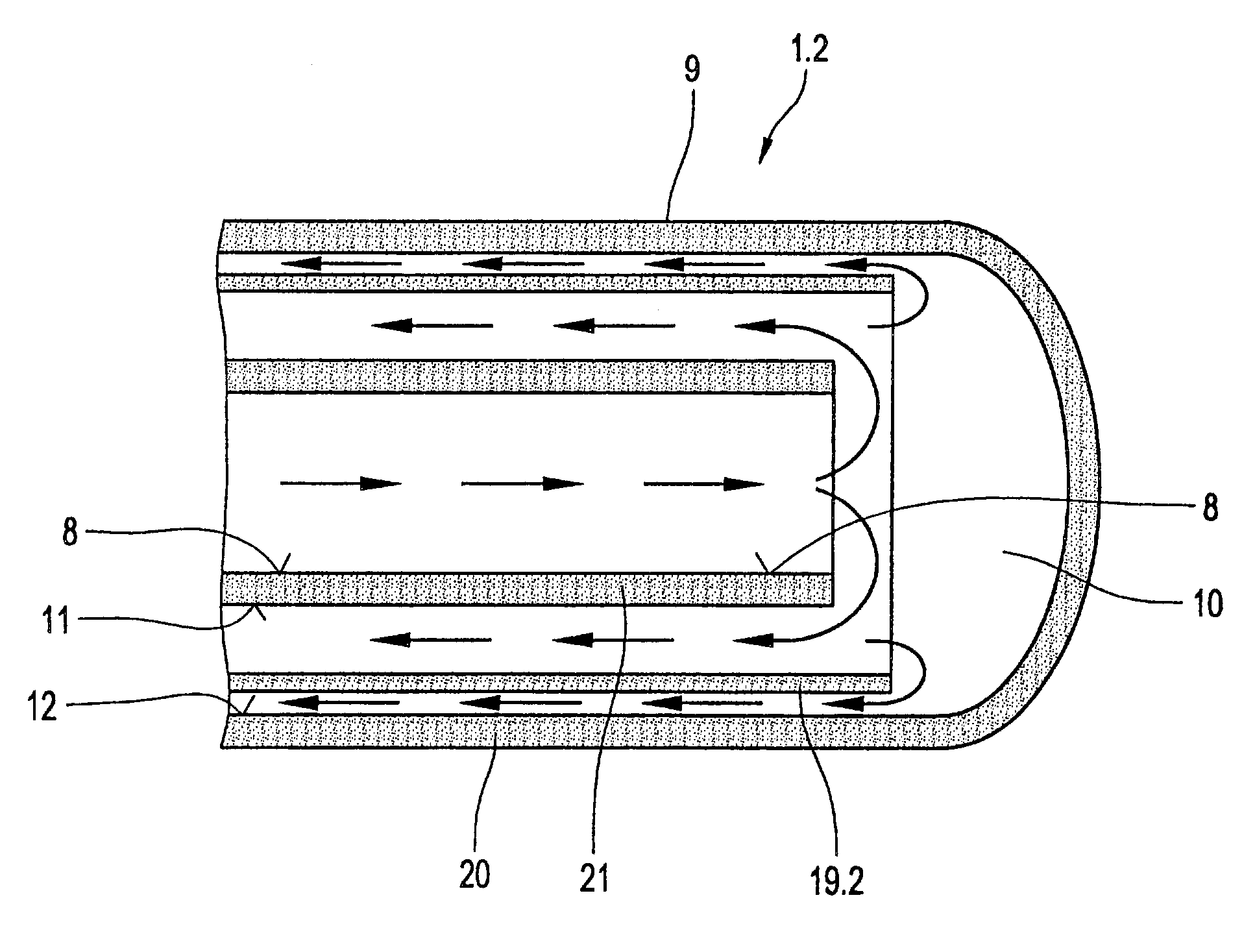
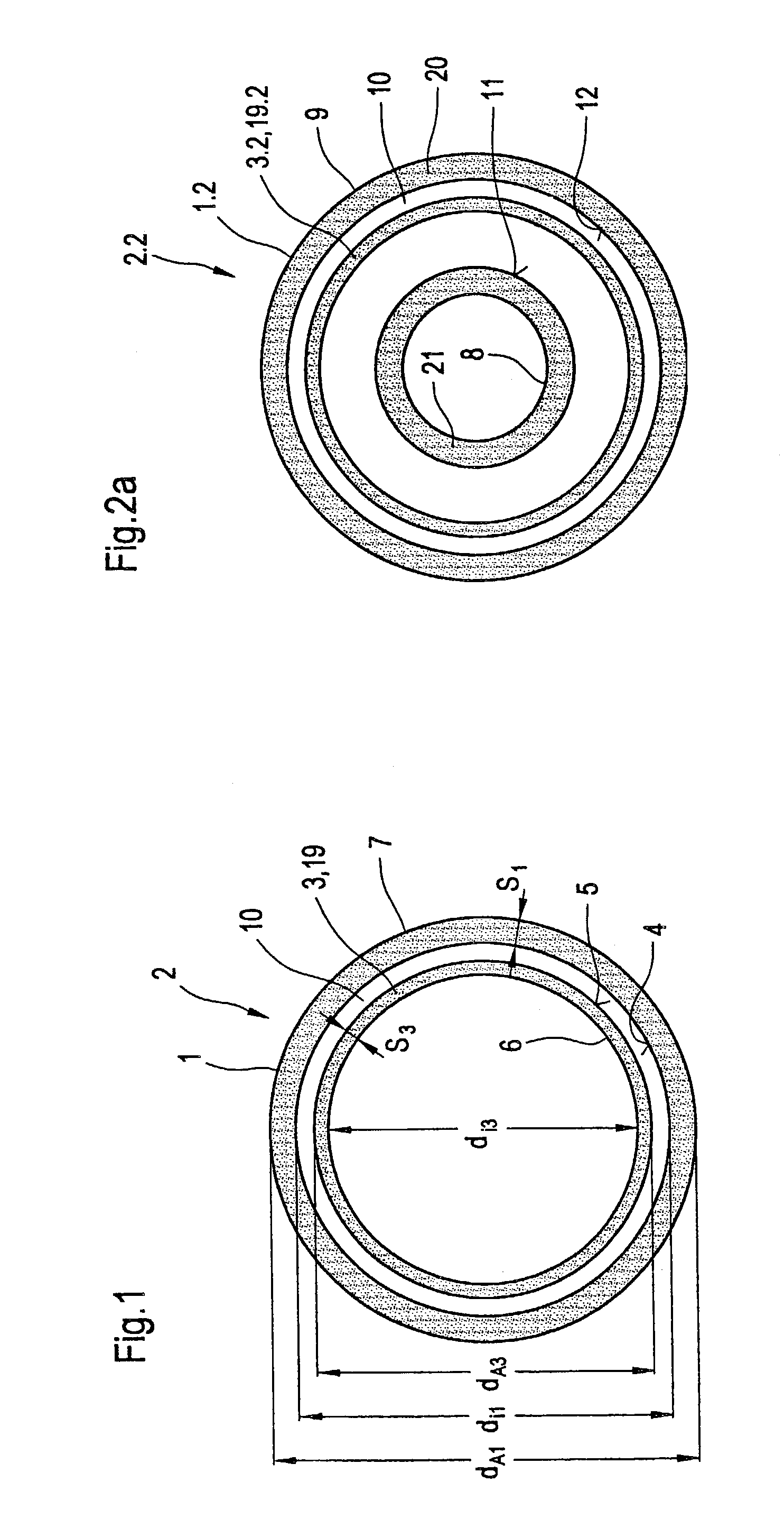
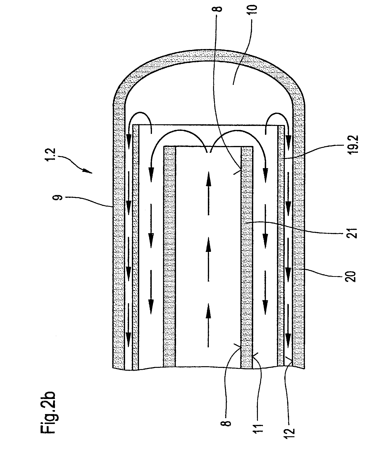
[0030]FIG. 1 illustrates an arrangement according to the invention using a diagrammatic simplified sectional view through a glass tube 1 to increase the thermal fatigue resistance of glass tubes through which fluid flows and are pressure-loaded. The arrangement is marked with 2. This comprises an interior component 3 in form of a thin-walled glass tube 19, which is slid into the glass tube 1 to be protected, in particular into the interior 10 surrounded by said glass tube. Glass tube 1 and interior component 3 are connected hydraulically with one another, i.e. the interior component 3 does not form an interior separate from the interior 10. The outside diameter dA3 of the thin-walled tube 19 is smaller than the inside diameter dI1, of the glass tube 1. In the condition of being flown through by fluid of the glass tube 1 both—both glass tube 1 and thin-walled tube 19—are free of a direct thermal connection by direct contact, in particular the inner surface 4 of the glass tube 1 chara...


PUM


Abstract

An arrangement to increase the thermal fatigue resistance of glass tubes having fluid flowing therethrough and being pressure-loaded. This arrangement comprises a glass tube, into which an interior component is inserted. The interior component can be designed as thin-walled tube or tubular component. In accordance with a first example the cavity enclosed by the interior component is hydraulically connected with the interior of the glass tube. The wall thickness of the interior component is smaller than the wall thickness of the glass tube and the interior component is partially free from a direct heat connection with the glass tube. In accordance with a second example the interior component increases the wall thickness of the glass tube. In this case the interior component is touching the interior circumference of the glass tube.

Description

BACKGROUND OF THE INVENTION[0001]The invention relates to an arrangement to increase the thermal fatigue resistance of glass tubes through which fluid flows and are pressure-loaded and the use of such an arrangement in a heat exchanger or an absorber tube for solar collectors.[0002]Tubular components made from glass are frequently used to guide a flow medium in heat exchangers and absorber tubes of solar collectors. The thermal fatigue resistance presents a substantial problem, whereby said thermal fatigue resistance can be described as a function of the type of glass, the geometrical design and the dimensioning. Such glass tubes must usually exhibit a minimum wall thickness due to the pressure prevailing in the interior. This leads to the fact that extreme temperature changes of the fluid flowing in the interior can lead to glass breaks due to the thermal conducting behavior of the tube wall and the associated stresses. In particular when filling an absorber tube made from glass in...

Claims


Application Information

Patent Timeline
Patent Type & Authority Patents(United States)
IPC IPC(8): F15D1/00F24J2/48F24S10/40F24S10/70F28F1/00F28F21/00
CPCF24J2/055F28F1/003F28F21/006Y02E10/44F24S10/45
Inventor BAUER, GUNTERBENZ, NIKOLAUS
Owner SCHOTT AG
Why Eureka
Try Eureka