Pressure resistant anechoic coating for undersea platforms

anechoic coating and pressure resistance technology, applied in the field of anechoic composites, can solve the problems of presently used composites that may collapse under shock pressure, deterioration of acoustic properties, time-varying shear and bulk deformation within the matrix, etc., and achieves small wall thickness, dissipation of acoustic energy, and resistance to deterioration

Inactive Publication Date: 2007-04-17
THE UNITED STATES OF AMERICA AS REPRESENTED BY THE SECRETARY OF THE NAVY
View PDF11 Cites 14 Cited by
  • Summary
  • Abstract
  • Description
  • Claims
  • Application Information

AI Technical Summary

Benefits of technology

[0014]It is a still further object of the present invention to provide a composite material for an undersea platform that absorbs acoustic energy directed toward the platform from an external source and thereby camouflages the existence of the platform.
[0015]It is a still further object of the present invention to provide a composite material that is resistant to deterioration due to the depth and shock pressures associated with undersea operations.
[0016]It is a still further object of the present invention to provide a composite material that is potentially insensitive to deterioration due to the depth and shock pressures associated with undersea operations.
[0017]It is a still further object of the present invention to provide a composite material with anechoic properties that can serve as a component of a structural element of a submarine sail.
[0018]In order to attain the objects described, there is provided a composite material composed of a syntactic foam matrix with inclusions of glass spherical shells embedded in the matrix in which each of the shells encapsulate a dynamically-active rubber core. The glass spherical shells are acoustically transparent at frequencies of interest and with their relatively small wall thickness cause only a slight modification to the resonance of the inclusions. The resonance of the rubber core with ferrite loading in combination with the matrix material dissipates acoustic energy directed toward the composite material.
[0019]Since the spherical shells are statically stiffer than the surrounding matrix material, the shells shield their encapsulated cores from background pressure and thereby allow a lower shear modulus for the cores. A lower shear modulus allows the use of the rubber-like core. The stiffness and spherical shape of the inclusions also make the composite material resistant to pressure and substantially increases the shock resistance of the composite material. As a result, a composite material is disclosed that will dissipate the power of an incoming sea wave and is resistant to undersea pressures as well as being able to dissipate acoustic energy.

Problems solved by technology

Acoustic waves incident upon the water-facing surface cause time varying shear and bulk deformations within the matrix.
The problem with presently used noise control technologies is that their acoustic properties deteriorate due to the large deformation of the rubber particles or other acoustic impedance particles under the depth and shock pressures associated with undersea operations.
As such a composite material as a noise control technology may be acceptable for sound absorption at one hydrostatic pressure or temperature and less effective at another.
Additionally, presently used composites may collapse under shock pressure due to the large shear deformation of the rubber particles.

Method used


Image

  • Pressure resistant anechoic coating for undersea platforms
  • Pressure resistant anechoic coating for undersea platforms

Examples


Embodiment Construction

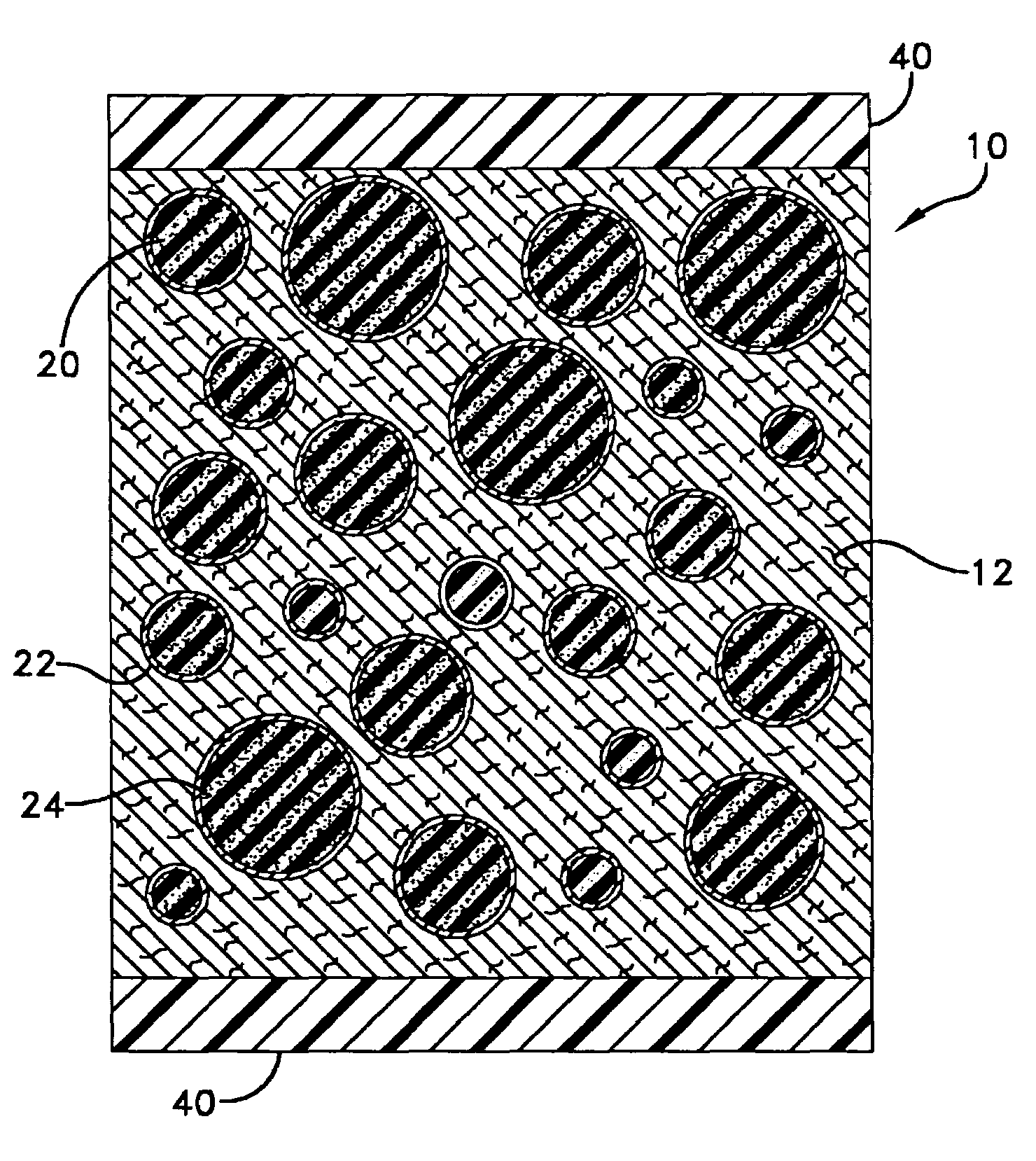
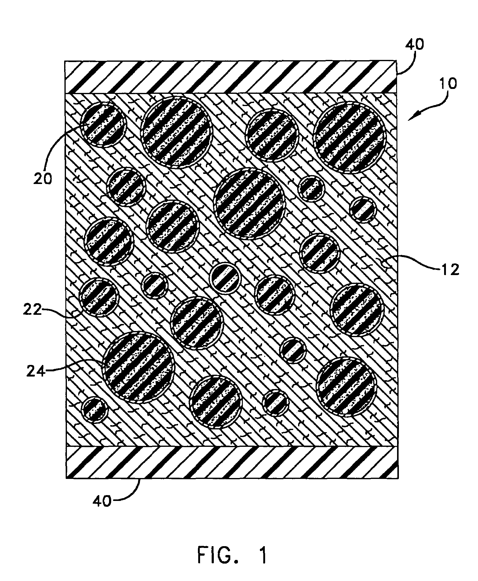
[0022]Referring now to the drawing wherein like numerals refer to like elements throughout the view, one sees that FIG. 1 depicts a composite material 10 of the present invention in which the composite material is contained by plates 40. The plates 40 are preferably fiberglass or an alternate composite material known to those skilled in the art. The combination of the plates 40 with the composite material 10, shown in the figure, can be used as a structural element such as a panel or shell used in the construction of an undersea vehicle (not shown).

[0023]The composite material 10 comprises a matrix material 12 having inclusions 20 of spherical shells 22 in which each shell encapsulates a dynamically-active core 24. The spherical shells 22 are preferably made of glass; however, any suitable substitute known to those skilled in the art may be used.

[0024]The core 24 is preferably TECHTHANE or a similar material known to those skilled in the art in which the core has rubber-like propert...


PUM

PropertyMeasurementUnit
bulk modulusaaaaaaaaaa
densityaaaaaaaaaa
acoustic energyaaaaaaaaaa

Abstract

A composite material containing inclusions of spherical shells in which each spherical shell encapsulates a rubber core with ferrite loading. The inclusions are embedded in a matrix material of syntactic foam. The spherical shells are made from glass and therefore acoustically transparent and in combination with the cores are statically stiffer than the surrounding matrix material. The composite material with the matrix material and inclusions allows the composite material to be acoustically dissipating with a stiffness in which the energy of forces associated with undersea platforms is resisted.

Description

STATEMENT OF GOVERNMENT INTEREST[0001]The invention described herein may be manufactured and used by or for the Government of the United States of America for Governmental purposes without the payment of any royalties thereon or therefore.BACKGROUND OF THE INVENTION[0002](1) Field of the Invention[0003]The invention relates to anechoic composites as a coating or as a component of a structural element for use on undersea platforms.[0004](2) Description of the Prior Art[0005]Presently, noise control technology for undersea vehicles includes external coatings in which the coatings absorb probing undersea sound waves produced by sonar transducers and thereby echoes of the undersea sound waves are minimized to prevent active detection of the undersea vehicles.[0006]In Rauh (U.S. Pat. No. 3,698,993), a foamed closed cell sheet elastomeric material with particulate material distributed there through is disclosed. The particulate material is composed of high density particles of variegated ...

Claims


Application Information

Patent Timeline
Patent Type & Authority Patents(United States)
IPC IPC(8): D04H1/00B32B3/26E04B9/00H04R25/00
CPCC08J9/32G10K11/165Y10T428/249924Y10T428/24994Y10T428/249953
Inventor SPERO, ARTHUR C.GODOY, CARLOS M.HARARI, AZRIELTEAGUE, JAMES M.
Owner THE UNITED STATES OF AMERICA AS REPRESENTED BY THE SECRETARY OF THE NAVY
Why Eureka
Try Eureka