Photoelectric encoder

a technology of photoelectric encoder and encoder, applied in the direction of converting sensor output optically, instruments, measurement devices, etc., can solve the problems of image division and reverse in each single lens optical system

Active Publication Date: 2006-09-14
MITUTOYO CORP
View PDF2 Cites 9 Cited by
  • Summary
  • Abstract
  • Description
  • Claims
  • Application Information

AI Technical Summary

Benefits of technology

[0011] Furthermore, various embodiments of this invention also provide a photoelectric encoder that can maintain not only image patterns but also shapes (a second object).
[0014] The focal position of each lens of the third lens array is smaller than the focal position of each lens of the first and second lens array to shorten the entire optical length.
[0020] According to the present invention, image patterns in an incremental type photoelectric encoder can be maintained by bringing the set pitches of respective lenses of a lens array into agreement with the period of the main scale or natural number multiple thereof.

Problems solved by technology

As shown in FIG. 3 and FIG. 5, however, when a photoelectric encoder employs the lens array 46, there was a problem in which the image was divided and reversed in each single lens optical system.
This is a problem with not only image patterns but is an especially serious problem with absolute types which are required to reproduce accurate shapes.

Method used


Image

  • Photoelectric encoder
  • Photoelectric encoder
  • Photoelectric encoder

Examples


first embodiment

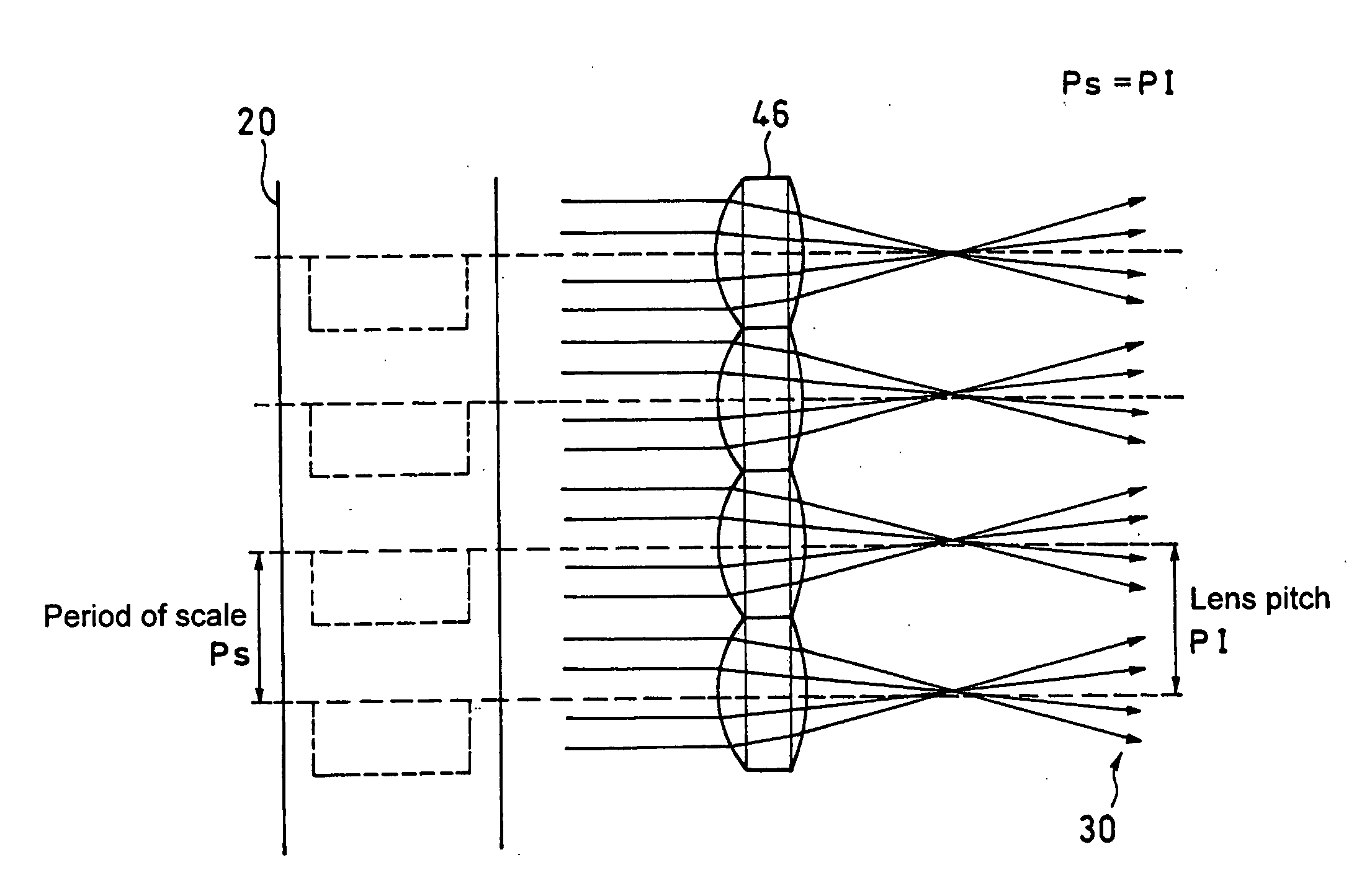
[0051] As shown in FIG. 6, according to the present invention, an incremental type photoelectric encoder has a lens array 46. The lens array 46 is composed of a plurality of lenses with a set pitch P1 (referred to as “lens pitch”) which is brought into agreement with a period Ps of a main scale 20 or natural number multiple thereof.

[0052] As shown in FIG. 7, in the present embodiment since the pattern is ensured even if the image is divided and reversed in each separate lens, there is no problem as long as it is used as an incremental type.

[0053] Further, as shown in FIG. 8, aperture 44 can be provided at focal point of each lens of the lens allay 46 so as to form a telecentric optical system 40.

second embodiment

[0054] Next, the present invention will be described with reference to FIG. 9 (light path view) and FIG. 10 (perspective view).

[0055] In the present embodiment, a second lens array 48 identical to the lens array 46 (first lens array) is provided in the reverse direction so as to make the focal points thereof be positioned at the positions where the focal points of the first lens array 46 are located, thereby forming an optical system 50.

[0056] In the present embodiment, the lens array 48 is the same as the lens array 46. Because of this, aberrations occurring on the first lens array 46 provided on the input side can be almost completely inversely corrected by the second lens array 48 provided on the output side. Therefore, even if a low-cost lens array with large aberrations is used, the aberrations can be almost completely cancelled and the signal detection efficiency can be greatly improved.

[0057] Further, as shown in FIGS. 11 and 12, aperture 44 can be provided at focal point o...

third embodiment

[0058] Next, the present invention will be described with reference to FIG. 13.

[0059] The present embodiment relates to an absolute type photoelectric encoder that has a lens array 46. In this photoelectric encoder, an image is electrically re-reversed by changing the output connection of a light receiving element array 34 by the pixels.

[0060] Further, as shown in FIG. 14, aperture 44 can be provided at focal point of each lens of the lens allay 46 so as to form a telecentric optical system 40.


PUM


Abstract

A photoelectric encoder is provided which has an optical system including a first lens array inserted between a main scale and a light receiving element. An image divided or reversed by the first lens array can be electrically or optically re-reversed. This can achieve the reduction of the entire size as well as increase in the scale field of view, while maintaining the image shape and / or pattern.

Description

CROSS-REFERENCE TO RELATED APPLICATION [0001] The disclosure of Japanese Patent Application No. 2005-69579 filed on Mar. 11, 2005 including specifications, drawings and claims is incorporated herein by reference in its entirety. BACKGROUND OF THE INVENTION [0002] 1. Field of the Invention [0003] The present invention relates to a photoelectric encoder. In particular, the invention relates to improvements in a photoelectric encoder that has a telecentric optical system wherein a lens and an aperture are inserted between a main scale and a light receiving element. [0004] 2. Description of the Related Art [0005] As described in Japanese Patent Laid-Open Publication No. 2004-264295 and as shown in FIG. 1, a photoelectric encoder is designed in which a lens optical system (telecentric optical system) 40, comprising a lens 42 and an aperture 44 that functions as a telecentric optical diaphragm, is inserted between a main scale 20 and a light receiving element array 34 constituting a light...

Claims


Application Information

Patent Timeline
Patent Type & Authority Applications(United States)
IPC IPC(8): G01D5/34
CPCG01D5/34784G01D2205/90
Inventor MIZUTANI, MIYAKO
Owner MITUTOYO CORP
Why Eureka
Try Eureka