Wireless mouse charger

a charger and mouse technology, applied in the field of wireless mouse chargers, can solve the problems of limited functions of conventional wireless mouse chargers, user's inability to view and operate peripheral devices, and inconvenient connection of peripheral devices to the back of the mainframe via connection cords, etc., and achieve the effect of increasing the practicability of such charging

Inactive Publication Date: 2006-09-14
CHANG YUAN JUNG
View PDF5 Cites 30 Cited by
  • Summary
  • Abstract
  • Description
  • Claims
  • Application Information

AI Technical Summary

Benefits of technology

[0011] The primary objective of the invention is therefore to specify a wireless mouse charger th

Problems solved by technology

It is inconvenient to connect peripheral devices to the back of the mainframe via connection cords.
It is more inconvenient to directly connect peripheral devices to the back of the mainframe without using connection cords, so that after connection, the user is unable to view and operate the peripheral devices.
The functions of the conventional wireless mouse c

Method used


Image

  • Wireless mouse charger
  • Wireless mouse charger
  • Wireless mouse charger

Examples


Embodiment Construction

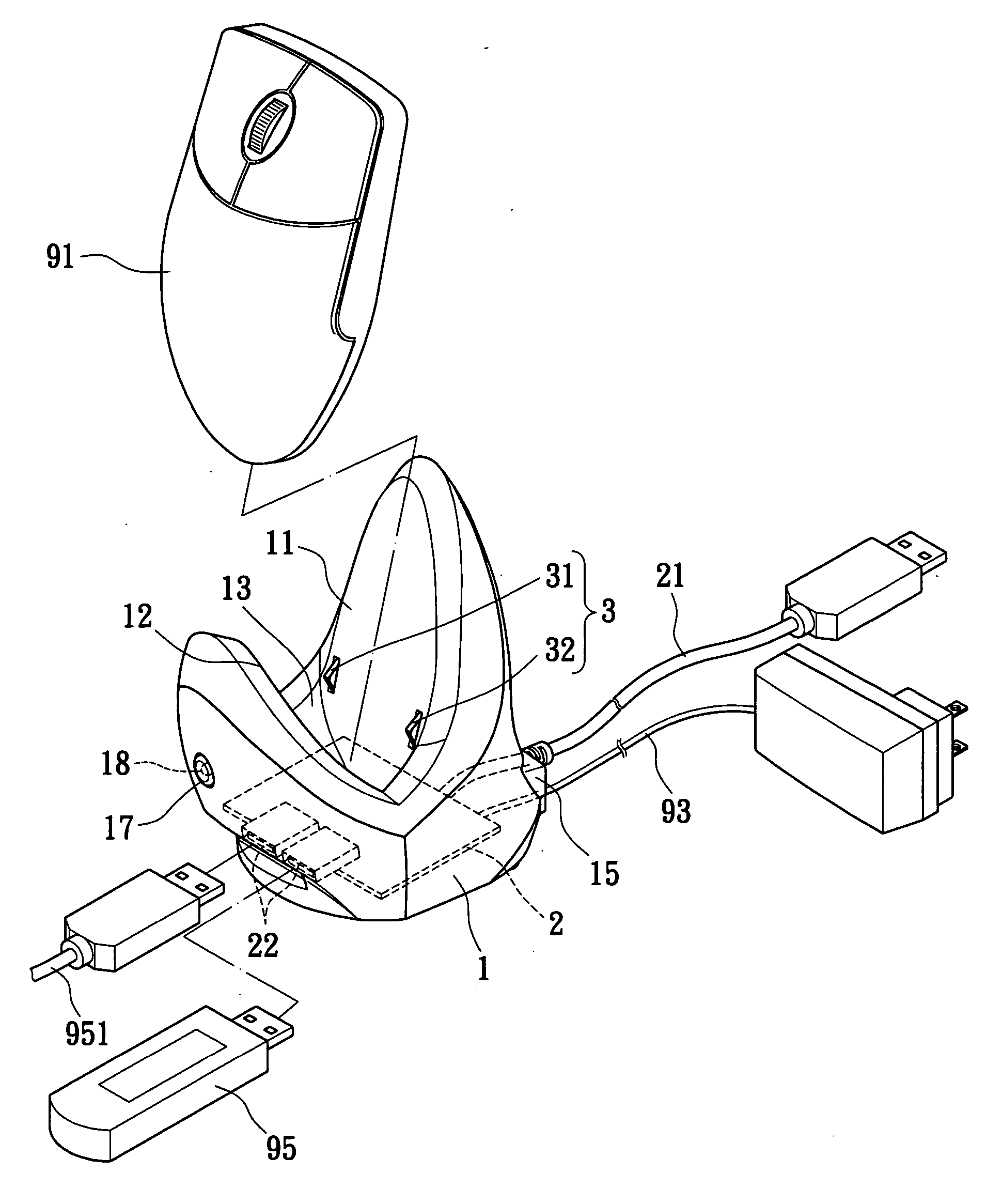
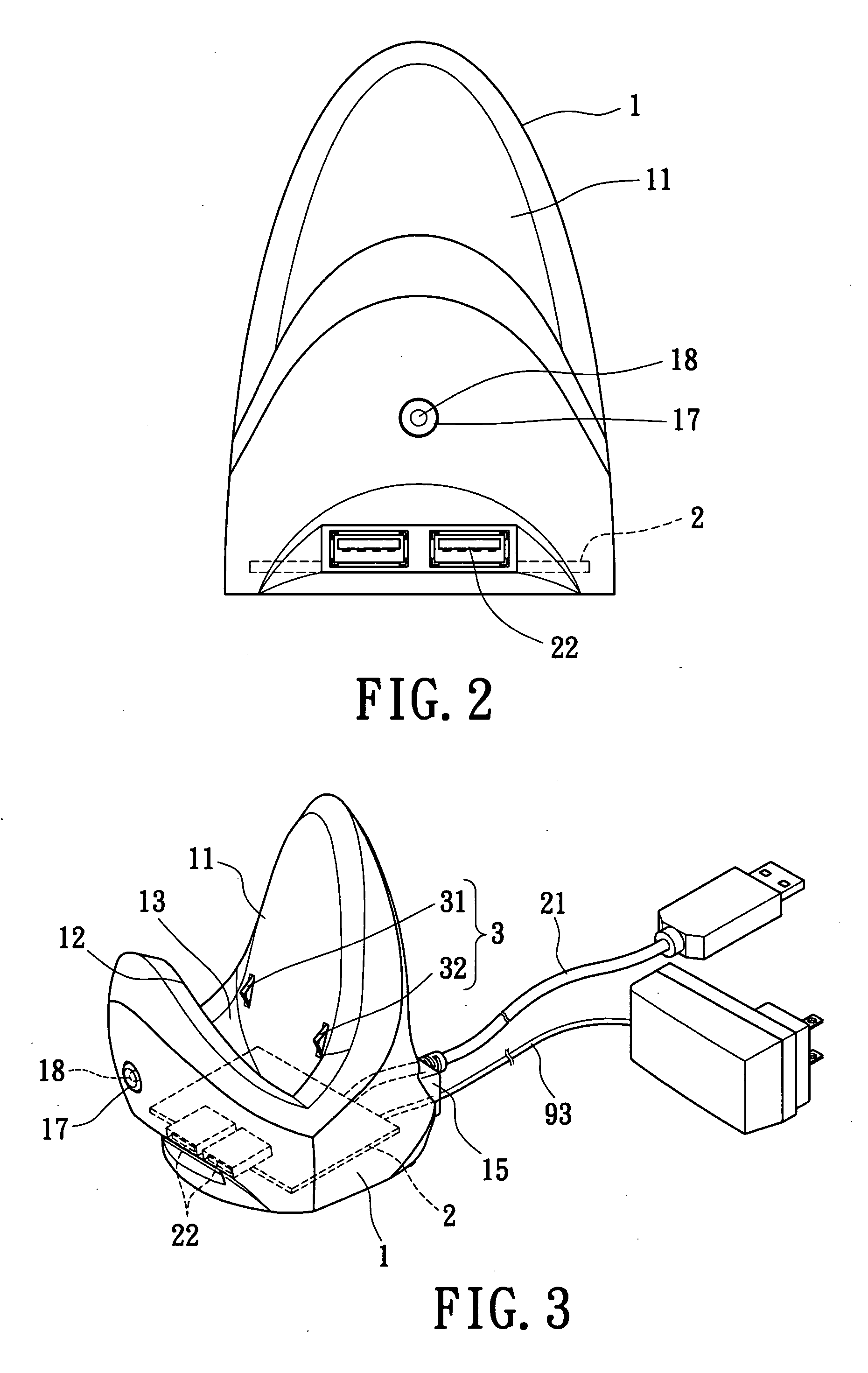
[0031] Referring to FIGS. 2-5, the present invention provides a wireless mouse charger. The wireless mouse charger comprises a housing 1, a circuit unit 2, a signal connection interface 21, an expansion transmission interface 22, and a first contact set 3.

[0032] The housing 1 has a first inner sidewall 11, a second inner sidewall 12, and a mouse cavity 13. The mouse cavity 13 is formed between the first inner sidewall 11 and the second inner sidewall 12. As shown in FIG. 4, the mouse cavity 13 is for receiving a rechargeable wireless mouse 91 therein.

[0033] The circuit unit 2 is disposed in the housing 1. The circuit unit 2 has a charge and over-charge protection circuit for processing the charging process of the rechargeable wireless mouse 91. The circuit unit 2 has a signal receiving circuit for processing the wireless signals generated by the rechargeable wireless mouse 91 when it is in use.

[0034] The housing 1 further has a signal connection key 17 electrically connecting the...


PUM


Abstract

A wireless mouse charger has a housing, a circuit unit, a signal connection interface, and an expansion transmission interface. The signal connection interface electrically connects to the circuit unit for connecting to a mainframe. The expansion transmission interface electrically connects to the circuit unit for connecting to a peripheral device. Connecting the peripheral device and the expansion transmission interface is very easy, and after the connection, the peripheral device is viewed and operated by the user simply.

Description

BACKGROUND OF THE INVENTION [0001] 1. Field of the Invention [0002] The present invention relates to a wireless mouse charger, and more particularly, to a wireless mouse charger that has the function of connecting with a peripheral device. [0003] 2. Description of Related Art [0004] A mainframe has a number of connectors for connecting various peripheral devices, such as an external disk driver, a personal digital assistant, a card reader, a recorder, a digital camera, a portable disk driver, and so forth. Generally, the connectors are arranged on the back of the mainframe. It is inconvenient to connect peripheral devices to the back of the mainframe via connection cords. Different peripheral devices have different keys, indication lamps, and display panels according to their functions. It is more inconvenient to directly connect peripheral devices to the back of the mainframe without using connection cords, so that after connection, the user is unable to view and operate the periph...

Claims


Application Information

Patent Timeline
IPC IPC(8): H02J7/00
CPCH02J7/0044H02J7/025H02J7/0045H02J5/00H02J7/02
Inventor CHANG, YUAN-JUNG
Owner CHANG YUAN JUNG
Why Eureka
Try Eureka