Integrated ocular examination device

a collimated image and integrated technology, applied in the field of ocular examination and therapeutic devices, can solve the problems of not providing electrostatic switching, the mirrors in this design do not rotate,

Inactive Publication Date: 2006-09-14
SHOWDH
View PDF16 Cites 34 Cited by
  • Summary
  • Abstract
  • Description
  • Claims
  • Application Information

AI Technical Summary

Benefits of technology

[0017] A further variant includes the provision of a two-segment mirror, which causes portions of substantially collimated beam paths to extend toward the eye at slight angles relative to each other, this being to accomplish measurement of a desired visual acuity of the patient's eye by inducing selective accommodation of the eye's crystalline lens. A virtual test screen can be spaced at a given focal length from the patient's eye and upon which may be projected upper and lower overlapping images, the degree of overlap determining a given visual acuity and focal distance. In addition to visual acuity testing capabilities, the imaging device of the present invention can be utilized to diagnose other pathologies and provide ocular therapy, such as in the form of flicker photometry, in order to stimulate the user's eye, creating psychoperceptual responses that can be used for diagnostic purposes.

Problems solved by technology

Of note, the pivot mirrors in this design are not micromirrors and do not provide for electrostatic switching.

Method used


Image

  • Integrated ocular examination device
  • Integrated ocular examination device
  • Integrated ocular examination device

Examples


Embodiment Construction

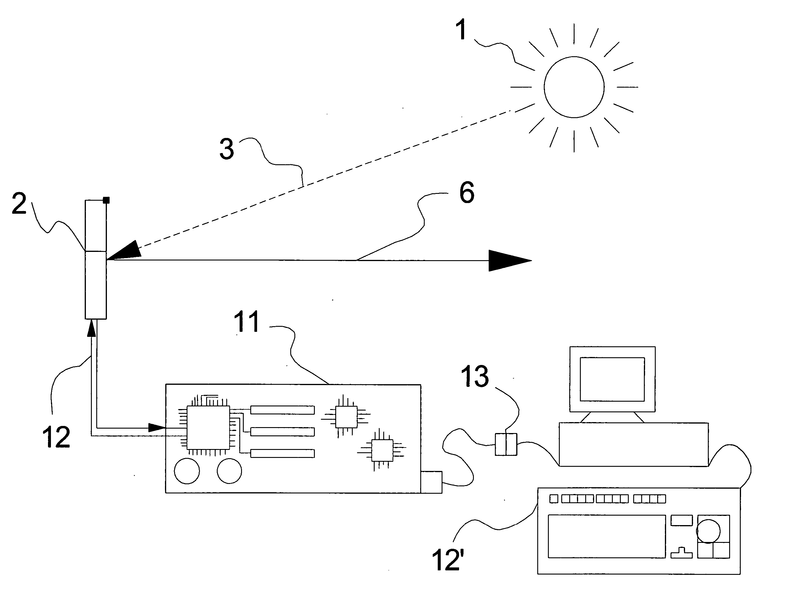
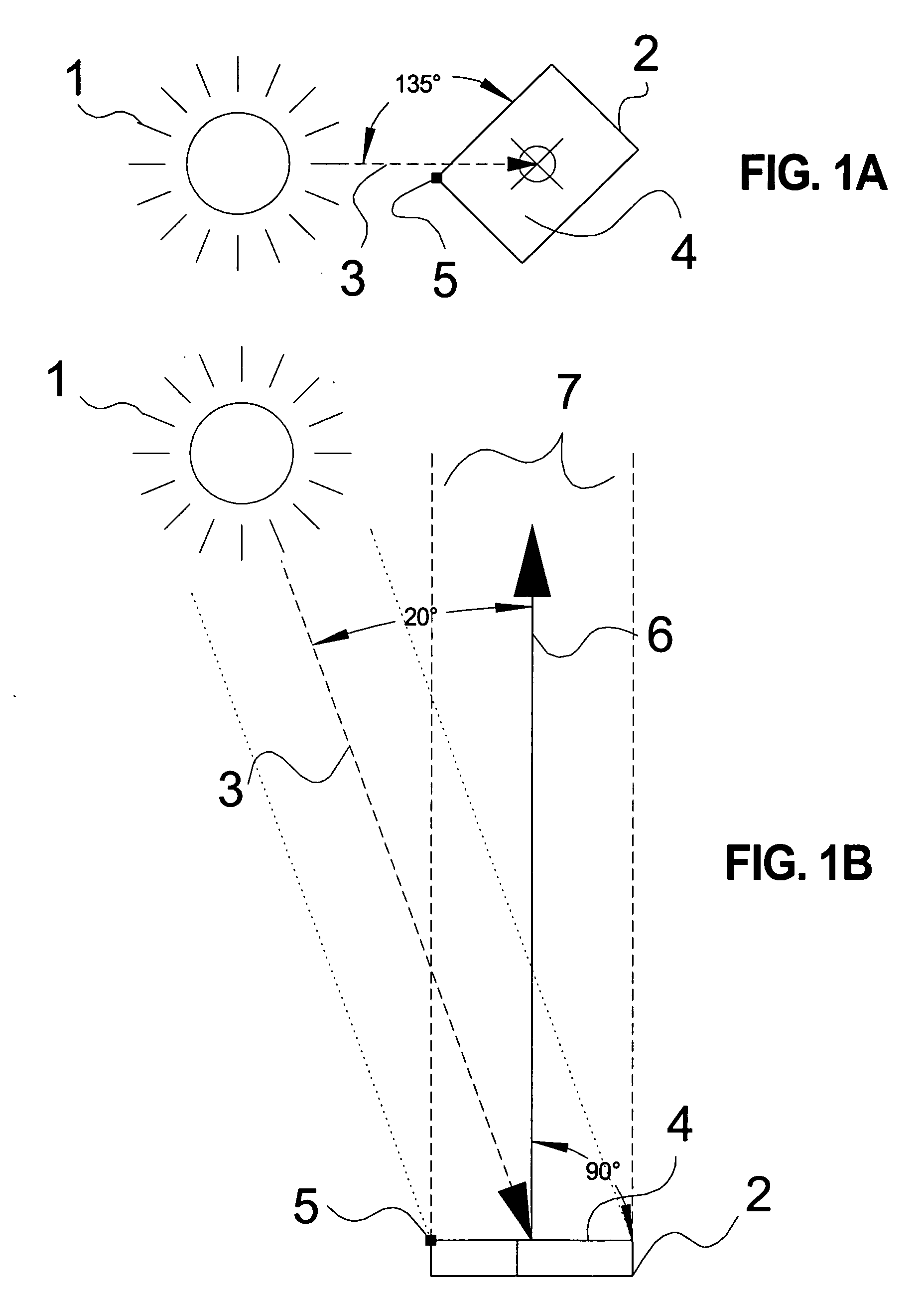
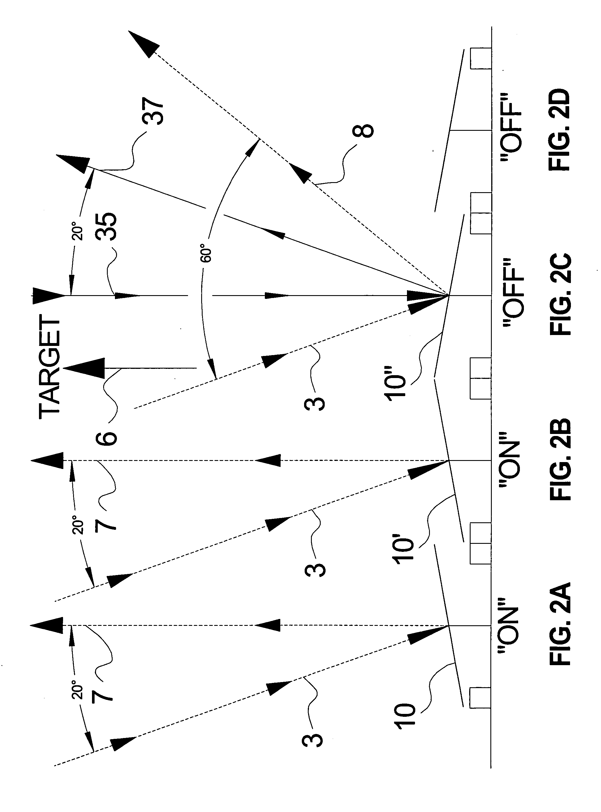
[0041] Referring now to FIG. 1A, a first representational illustration is shown of a collimated light source 3 projected upon a selected face 4 of a digital micromirror device 2 (hereinafter DMD), such typically including a plurality of micromirrors individually formed on the face 4, according to a first preferred embodiment of the present invention with the face 4 of the DMD 2 pointed out of the page. As previously explained, the adaptive collimated image device incorporates the features of a collimated light source and digital micromirror device, in order to combine the functional aspects of a number of ophthalmic tools into a single condensed enclosure digitally managed and interfaceable with hardware / software components.

[0042] A light or illuminating source is generally referenced at 1 and, in a preferred embodiment, may be constructed of components similar to those used in a digital light processing (or DLP) projector. Although not shown, such components may include a bulb wit...


PUM


Abstract

An imaging device for use in ocular investigations and including a body incorporating a light creating projector for issuing a collimated light source. A digital micromirror device being positioned to intercept the collimated light source, the micromirror device reflecting the light source in a specified pattern and in at least one of first and second directions. A control system connected to the micromirror device and interfacing with at least one processor driven input / output device, the control system selectively reflecting the pattern in directions towards and away from a patient's eye.

Description

BACKGROUND OF THE INVENTION [0001] 1. Field of the Invention [0002] The present invention relates generally to ocular examination and therapeutic devices. More specifically, the present invention teaches an adaptive collimated image device, incorporating the features of a collimated light source and digital micromirror device, and which combines the functional aspects of a number of ophthalmic tools into a single condensed enclosure digitally managed and interfaceable with hardware / software components. The collimated light waves are incident upon the digital micromirror device (DMD) at such an angle to each individual micromirror and to give rise to one of at least two reflected paths. [0003] 2. Description of the Prior Art [0004] The prior art is well documented with various examples of digital imaging devices. Central to such applications is the digital micromirror device (DMD) which consists of a two-dimensional array of micromirrors on the order of a 16 μm (micrometer) square et...

Claims


Application Information

Patent Timeline
Patent Type & Authority Applications(United States)
IPC IPC(8): A61B3/10
CPCA61B3/10
Inventor SQUIRE, BRET C.PATHAK, BOGDANMALPURE, SANDESH
Owner SHOWDH
Why Eureka
Try Eureka