

Optical fiber, optical fiber connecting method, and optical connector
- Summary
- Abstract
- Description
- Claims
- Application Information
AI Technical Summary
Benefits of technology
Problems solved by technology
Method used
Image

Examples
first embodiment
[0155] As another embodiment, there is explained the case where the PCF 11 is connected to a ferrule for FC connectors.
[0156]FIG. 3 is a cross-sectional view of a ferrule 30 for FC connectors to which the PCF 11 is connected.
[0157] As illustrated in FIG. 3, the ferrule 30 which is a component to compose an optical connector comprises a fixing portion 31 for fixing the PCF 11 with the cover 15 stripped, and a fiber-holding portion 32 into which the cover 15 of the PCF 11 is fitted. The FC-connector ferrule 30 with a cylindrical shape is used for single-core optical connectors. The PCF 11 is fixed to the fixing portion 31 of the ferrule 30 though an adhesive. The ferrule 30 with the PCF 11 fitted therein is connected to an optical connector, and, in the case of an FC connector, is fixed to the optical connector through a fastening portion 33 such as a screw and a pressure spring.
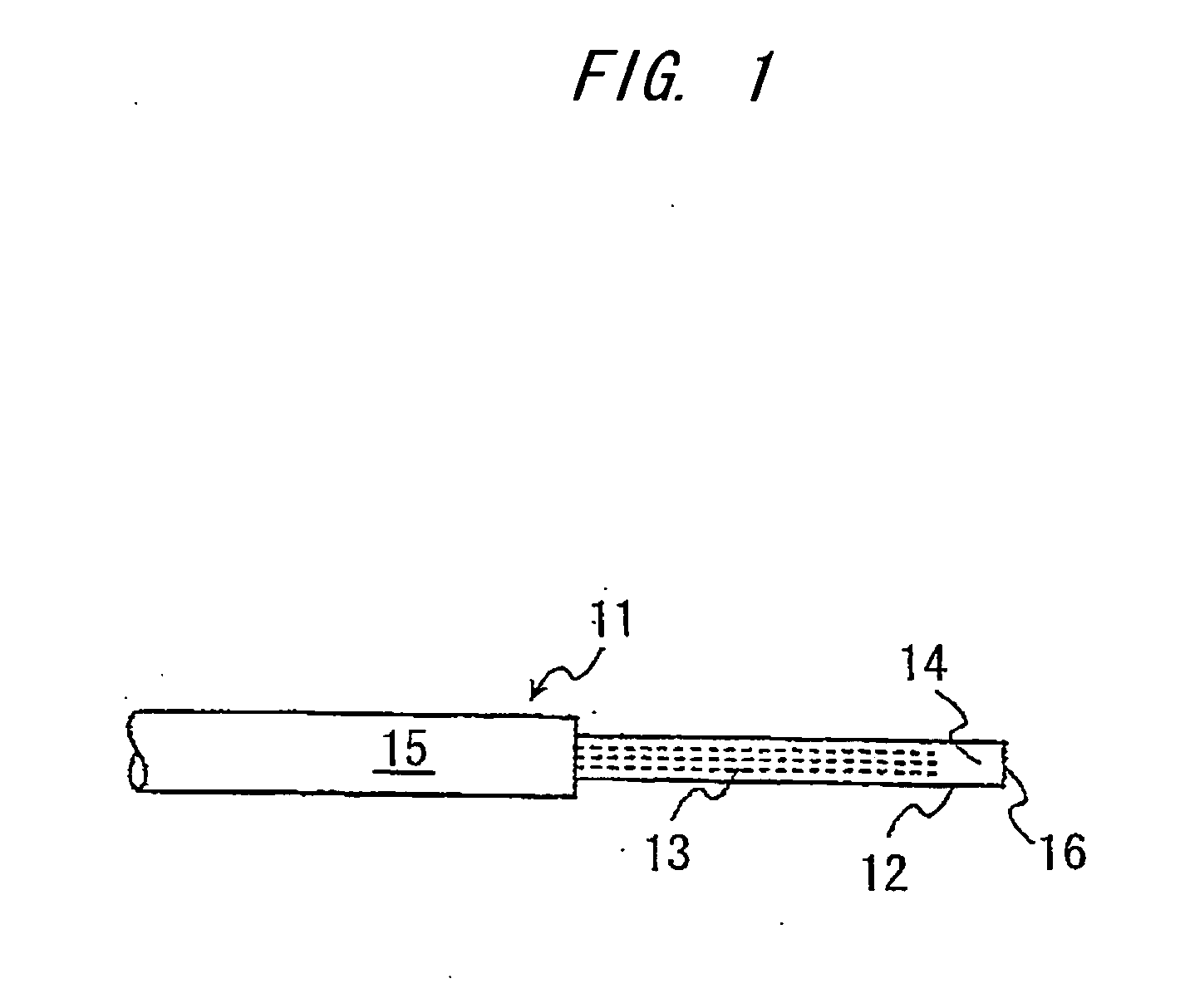
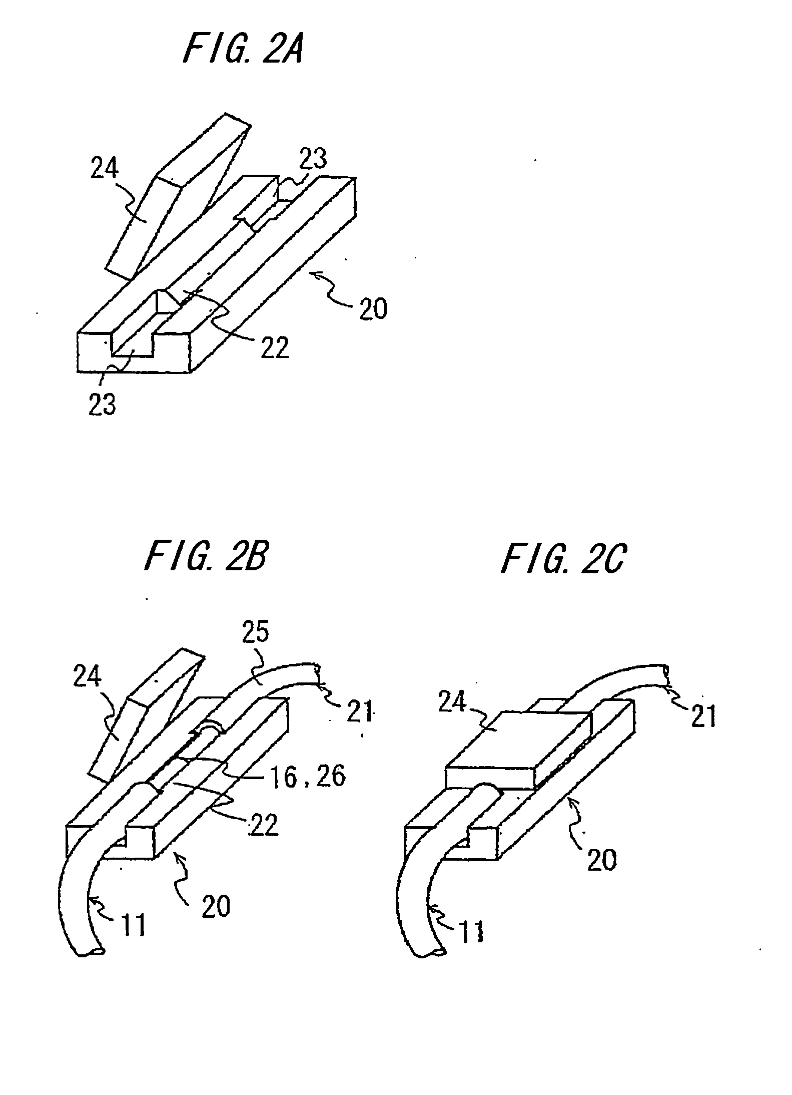
[0158] The proximity 12 of the connecting end of the PCF 11 with the UV-curable resin 14 filled therein ...
second embodiment
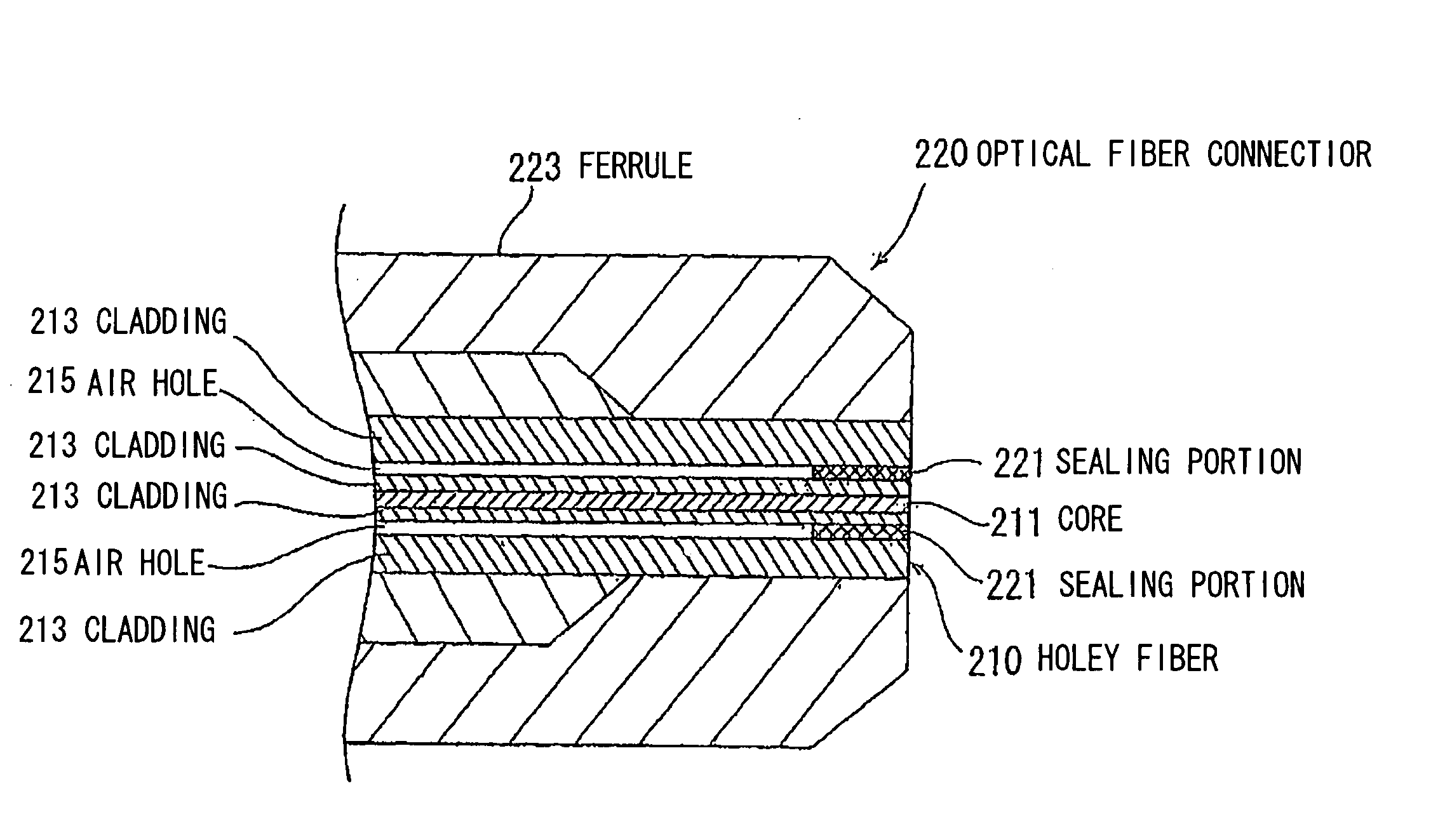
[0164]FIG. 7 is a longitudinal cross-sectional view illustrating the sealing structure for the end of the optical fiber according to the invention. FIG. 7 illustrates a more enlarged view of the optical fiber end than in FIG. 6. In the sealing structure for this optical fiber end, the respective fore-ends of the air holes 104 extending in the fiber axial direction are sealed by a sealing portion 105. This sealing portion 105 is formed in a recessed position of the end face of the Holey fiber 101, i.e., in a slightly inner position from the end face. Also, the diameter of the cladding 103 is totally the same in both positions in which are respectively formed the sealing portion 105 and the air holes 104. Further, although the two air holes 104 are sealed by the sealing portion 105 in FIG. 7, the ends of the other two air holes 104 not illustrated are likewise sealed.
[0165] The sealing method for realizing the sealing structure for this optical fiber end will be explained below.
[0166...
third embodiment
[0171]FIG. 8 illustrates a sealing structure for an end of an optical fiber according to the invention. In this sealing structure, fore-ends of axially extending air holes 104 are also sealed by a sealing portion 106. Also, the diameter of cladding 103 is totally the same in both positions in which are respectively formed the sealing portion 106 and the air holes 104. Further, a recessed portion of the end of a Holey fiber 101 is slightly deeper than the recess of FIG. 7.
[0172] The method for forming this sealing portion 106 is as follows: At the end of the Holey fiber 101, an end face is formed substantially at right angles to its axial direction, followed by partial heat treatment of the end face by the above-mentioned carbon dioxide gas laser without inserting glass powder. This allows an inflow of fused cladding material from the end face to seal the air holes.
[0173] In this case, as illustrated in FIG. 6, since the opening area of the air holes 104 is sufficiently smaller than...
PUM
 Abstract
Description
Claims
Application Information