Cleaning device

Inactive Publication Date: 2006-09-14
AVET
View PDF5 Cites 7 Cited by
  • Summary
  • Abstract
  • Description
  • Claims
  • Application Information

AI Technical Summary

Benefits of technology

[0009] It is an object of the invention to provide a cleaning device by which the application and distribution of cleaning fluid can be carried out in a time-saving and convenient manner

Problems solved by technology

The flat surface distribution of the cleaning fluid emerging from the outlet aperture, however, still requires substantial expenditure of time and labor.
The spray strip is arranged close to the floor, on at least one longitudinal edge of the retaining plate, and therefore close to the cleaning area, with the result that the risk pertains of the outlet apertures of the spray st

Method used


Image

  • Cleaning device
  • Cleaning device
  • Cleaning device

Examples


Example

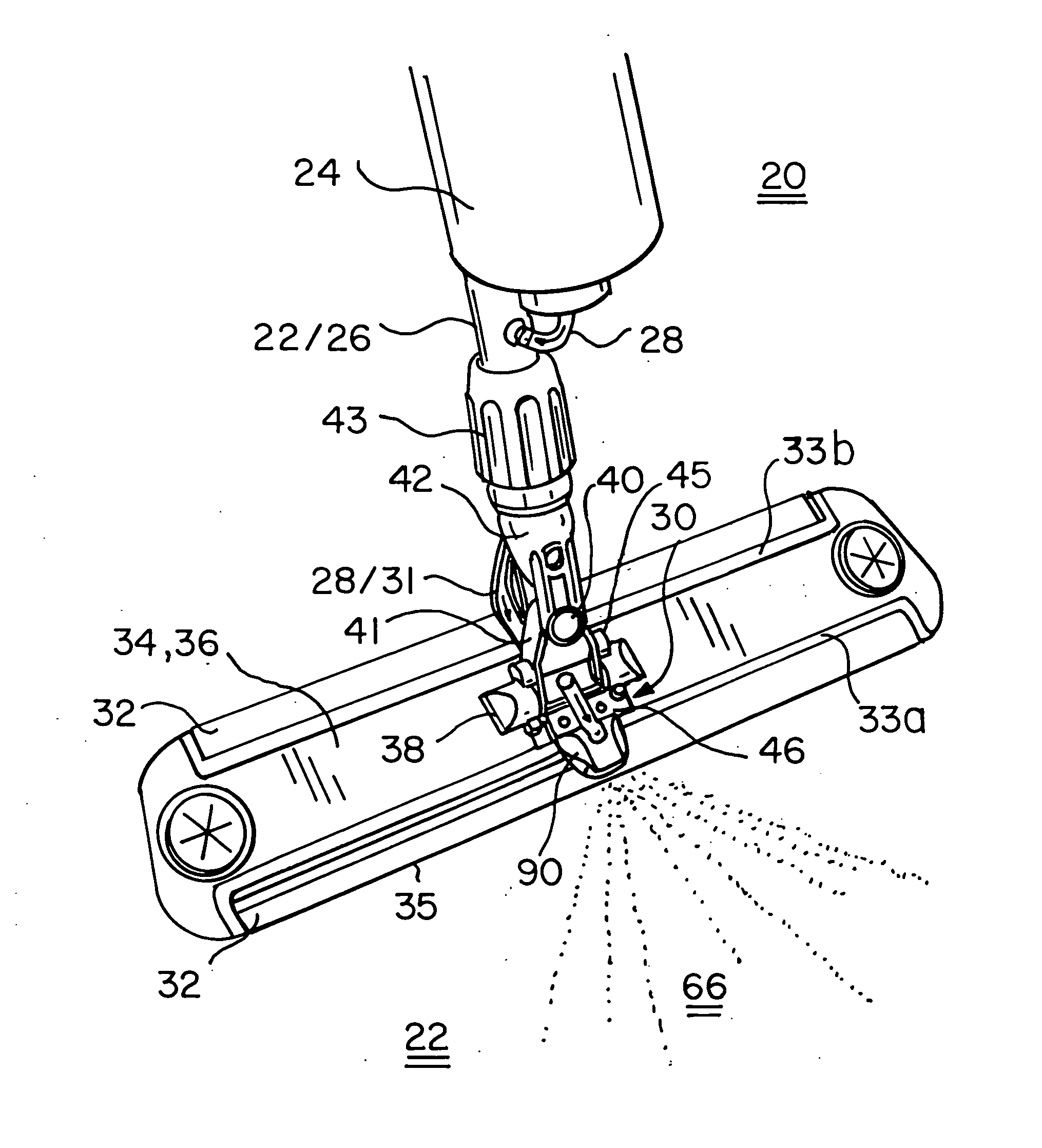
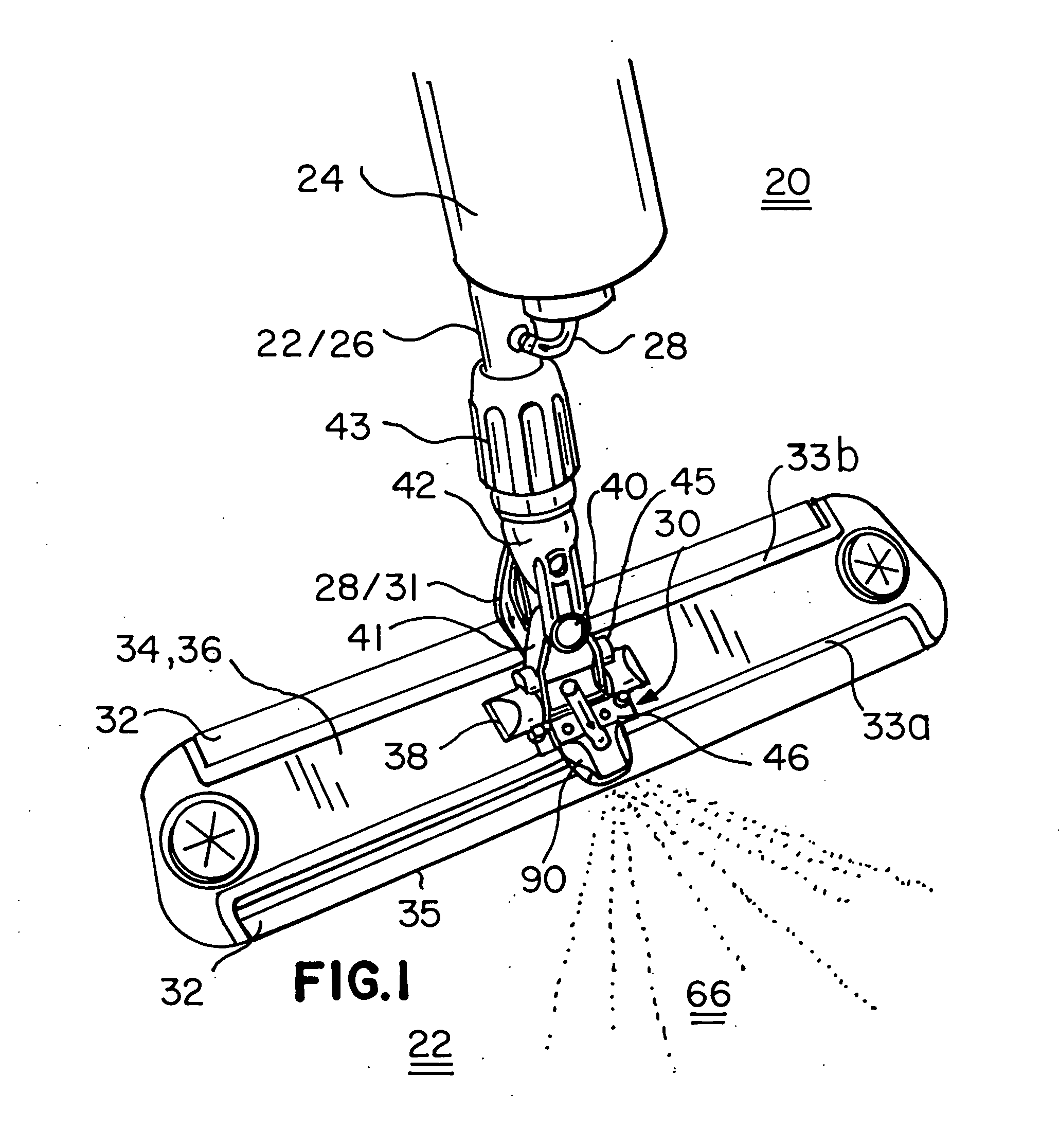
[0024] In one embodiment, the present invention provides a cleaning device, more particularly a flat mop. As shown in FIGS. 1-3 and 4, flat mop 20 comprises a support shaft 22, a retaining plate 34 connected to a distal end 26 of support shaft 20 by pivot means; a cleaning pad 80 detachably secured to a lower surface of retaining plate 34; a fluid reservoir 24 attached to support shaft 22 for holding fluid 28; and a flat jet spray assembly 30 secured upon upper surface 36 of retaining plate 34. Retaining plate 34 is also commonly referred to as flat mophead.

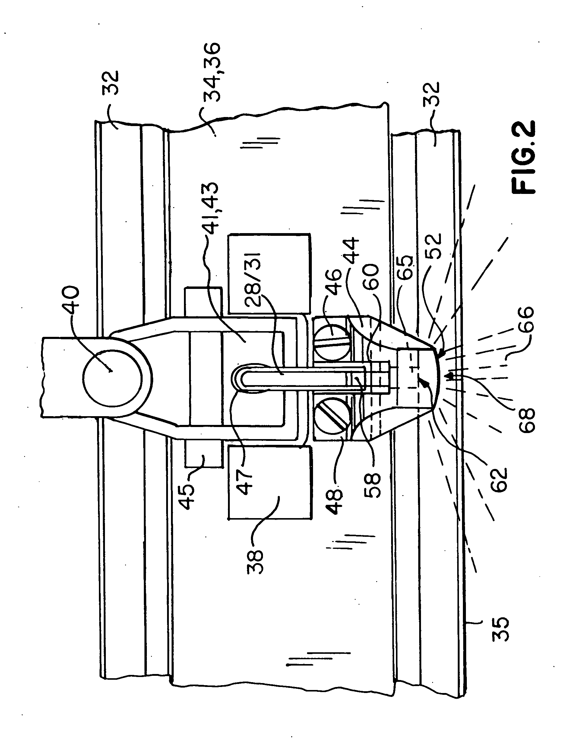
[0025] Further shown by FIGS. 1-3 is the connection mechanism between retaining plate 34 and support shaft 22, which includes a retaining element 38, a vertical pivot joint 41 retained by retaining element 38, a horizontal pivot joint 40 connected to the upper portion of vertical pivot joint 36, and a shaft mount 43 connected to upper portion 42 of horizontal pivot joint 40. Distal end 26 of support shaft 22 is secured into shaf...


PUM


Abstract

A cleaning device includes a support shaft; a retaining plate connected to a distal end of the support shaft by pivot elements; a cleaning pad detachably secured to a lower surface of the retaining plate; a fluid reservoir attached to the support shaft; and a flat jet spray assembly secured upon the upper surface of the retaining plate within its perimeter. The flat jet spray assembly includes a spray head having a securing flange with an inclined base at the rear portion; and a front portion having a slot-shaped spray jet outlet being open at side edges and a channel around a center of, and in perpendicular to, the slot-shaped spray jet outlet; a spray nozzle disposed within the channel, which has a horizontal emission slit; and a fluid feed tubing connected between the fluid reservoir and the spray nozzle.

Description

CROSS REFERENCE TO RELATED APPLICATION [0001] This application claims foreign priority benefits under 35 USC §119(a)-(d) or §365(b) of German Utility Model No. 20 2005 004 060.6, filed on Mar. 14, 2005. This application is also a Continuation-in-part of patent application Ser. No. 11 / 359,717, filed on Feb. 22, 2006, which is incorporated by reference herein in its entirety.FIELD OF INVENTION [0002] The present invention relates to a cleaning device, or flat mop, with a retaining plate serving as a carrier for cleaning cloths, mops, and similar cleaning elements, which is connected with a rod or similar handling device, as well as with a flat jet spray assembly attached to the retaining plate for the emission of cleaning fluid. BACKGROUND OF INVENTION [0003] Cleaning devices are already known which, by means of an emission device, emit cleaning fluid out of an outlet aperture onto the area of the floor located in front of the retaining plate. With a cleaning cloth arranged at the ret...

Claims


Application Information

Patent Timeline
IPC IPC(8): A47L13/30A47L13/22
CPCA47L13/22B05B1/044
Inventor SACKS, ROLAND
Owner AVET
Why Eureka
Try Eureka