Door of pet cage

Active Publication Date: 2018-12-06
LIANG HONGKUN
View PDF10 Cites 2 Cited by
  • Summary
  • Abstract
  • Description
  • Claims
  • Application Information

AI Technical Summary

Benefits of technology

[0013]As compared with the prior art, the present utility model has the following advantages.
[0014]1. A door bolt on a door stop of the present utility model can fit with an insertion buckle on a door frame, and a turning-back bar spaced from the door bolt also can be in insertion fit with the insertion buckle on the door frame, so when the door bolt fits with the insertion buckle, the turning-back bar is in inserted connection with an insertion buckle at another place of the door frame. Therefore, when a door of a pet cage is locked, multiple locking points are provided, so as to ensure locking firmness of the door of the pet cage and to guarantee that a pet cannot escape.
[0015]2. A latch of the present utility model is rotationally connected to a vertical bar through a reducing sleeve on the vertical bar, so the latch can rotate relative to the vertical bar, and after a handle is pulled to rotate, the handle can engage with or disengage from an engaging position on a door stop. Therefore, when the latch is inserted into the insertion buckle, the handle engages with the engaging

Problems solved by technology

However, when locking, the traditional latch has only one loc

Method used


Image

  • Door of pet cage
  • Door of pet cage
  • Door of pet cage

Examples


Example

Embodiment 1

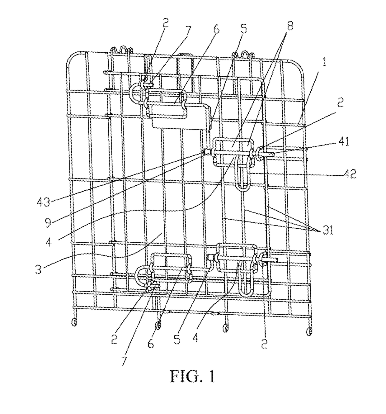
[0021]As shown in FIG. 1, a door of a pet cage includes a door frame 1 disposed on a cage body, where the door frame 1 is provided with multiple insertion buckles 2 protruding toward one side of the door frame 1, the door frame 1 is further provided with a door stop 3 capable of rotating relative to the door frame 1 to close same, the door stop 3 is provided with a door bolt 4 capable of transversely sliding relative to same, one end of the door bolt 4 can be in insertion fit with one of the insertion buckles 2, the other end of the door bolt 4 is connected to a vertical bar 5 capable of transversely moving relative to the door stop 3 along with the door bolt 4, the end portion of the vertical bar 5 is provided with a transverse bar 6 that extends toward one side of the vertical bar 5, the end portion of the transverse bar 6 is provided with a turning-back bar 7 that extends toward one side of the vertical bar 5 and keeps spaced from the transverse bar 6, and the turning...

Example

Embodiment 2

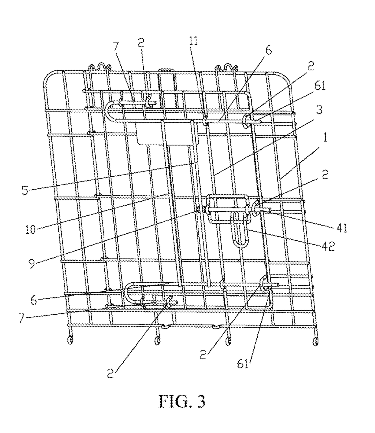
[0026]As shown in FIG. 3, the difference between Embodiment 2 and Embodiment 1 is as follows.

[0027]The middle of the vertical bar 5 is rotationally connected to the latch 41 through the reducing sleeve 9, the upper end and the lower end of the vertical bar 5 are provided with the transverse bar 6 separately, the middle of the transverse bar 6 is connected to the vertical bar 5, one end of the transverse bar 6 is connected to the turning-back bar 7, the other end of the transverse bar 6 is provided with an insertion segment 61 capable of being in inserted connection with the insertion buckle 2 on the door frame 1, and the outer side of the vertical bar 5 is further provided with a reinforcing bar 10 connected to the transverse bar 6. Therefore, the upper and lower portions of the door stop 3 both fit with the insertion buckles 2 on the door frame 1 through the turning-back bar 7 and the insertion segment 61 respectively, and the middle of the door stop 3 fits with the ins...


PUM


Abstract

A pet cage door, including a door frame disposed on a cage body, where door frame has multiple insertion buckles protruding toward one side of door frame, the door frame has a door stop capable of rotating relative to door frame to close same, the door stop has a door bolt capable of transversely sliding relative to same, one end of door bolt can be inserted with one of the insertion buckles, the door bolt's other end is connected to a vertical bar capable of transversely moving relative to the door stop along with door bolt, the vertical bar's end portion has a transverse bar that extends toward one side of the transverse bar, the transverse bar's end portion has a turning-back bar that extends toward one side of vertical bar and keeps spaced from transverse bar, and the turning-back bar can be inserted with door frame's other insertion buckle.

Description

BACKGROUNDTechnical Field[0001]The present utility model relates to a door of a pet cage.Related Art[0002]Nowadays, many people may keep small animals as pets in today's society. In this case, pet cages become necessities naturally. In order to prevent a pet from escaping from a cage, a cage door of a traditional pet cage is usually locked by using a latch. However, when locking, the traditional latch has only one locking point, which cannot firmly lock the door of the pet cage.[0003]Therefore, the present utility model is generated based on the foregoing disadvantages.SUMMARY[0004]An objective of the present utility model is to overcome disadvantages in the prior art to provide a door of a pet cage having a simple structure and being firmly locked.[0005]The present utility model is implemented by means of the following technical solutions.[0006]A door of a pet cage includes a door frame 1 disposed on a cage body, where the door frame 1 is provided with multiple insertion buckles 2 ...

Claims


Application Information

Patent Timeline
IPC IPC(8): E05C9/02E05C9/18A01K1/03
CPCE05C9/028E05B13/002A01K1/033E05C9/1808E05B63/143E05C1/04
Inventor LIANG, HONGKUN
Owner LIANG HONGKUN
Why Eureka
Try Eureka