Receptacle cage and method for making the same

Inactive Publication Date: 2010-04-01
HON HAI PRECISION IND CO LTD
View PDF7 Cites 17 Cited by
  • Summary
  • Abstract
  • Description
  • Claims
  • Application Information

AI Technical Summary

Benefits of technology

[0019]An advantage of the present invention provides a receptacle cage having a conductive plate so that the receptacle cage is securely grounded to a chassis and the conductive plate having a connection portion to increase stiffness of the conductive plate.
[0020]Another advantage of the present invention provides a method for making a rece

Problems solved by technology

Although solder reflow is an effective technique for electrically connecting a module to a circuit board, the heat required to achieve reflow tends to be detrimental to heat sensitive components within the module, such as plastic optical components which tend to warp or otherwise distort at high temperatures.
Furthermore, to ensure that modules are capable of withstanding the environmental conditions associated with reflow soldering, the industry utilizes high temperature materials that add cost to the modules.
The need for hand soldering, however, dramatically increases the cost of system comprising such modules.
Aside from the problems associated with soldering the module to the circuit board, there is the added inconvenience that, if a single module fails on a circuit board, which may support many such modules, the entire circuit board must be removed for service.
Although these conventional pluggable designs have been used successfully in the past, they tend to be

Method used


Image

  • Receptacle cage and method for making the same
  • Receptacle cage and method for making the same
  • Receptacle cage and method for making the same

Examples


Embodiment Construction

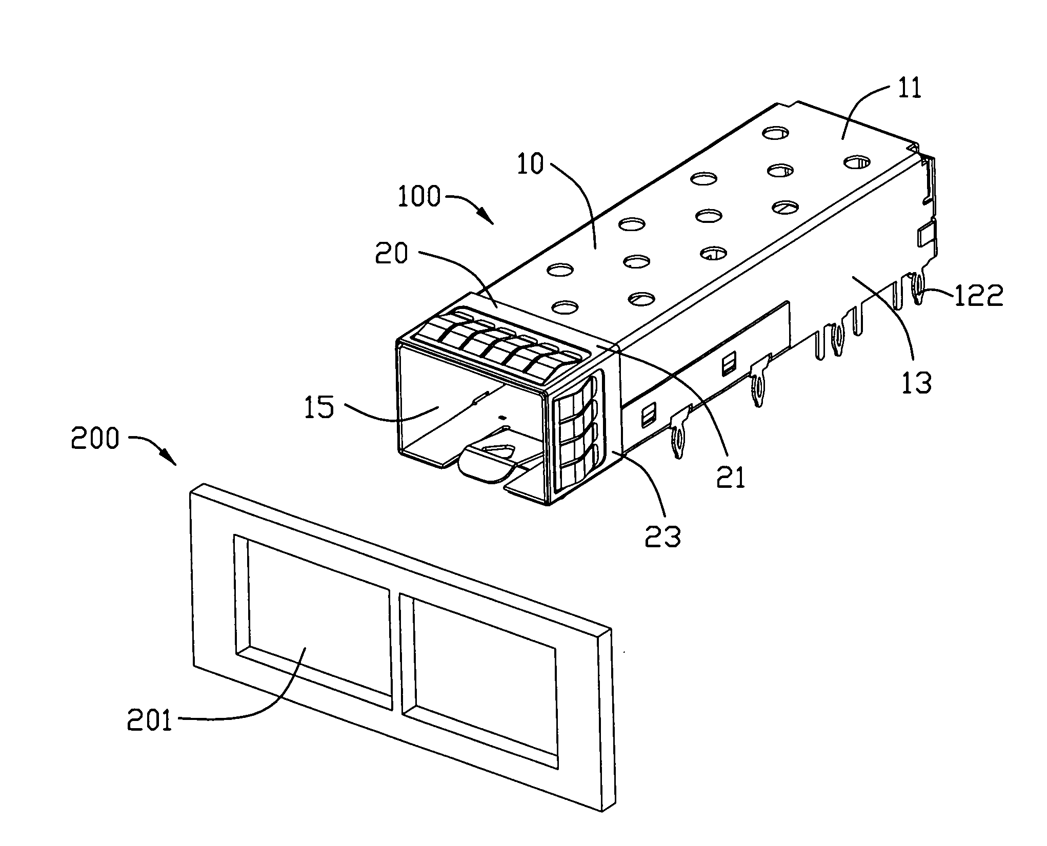
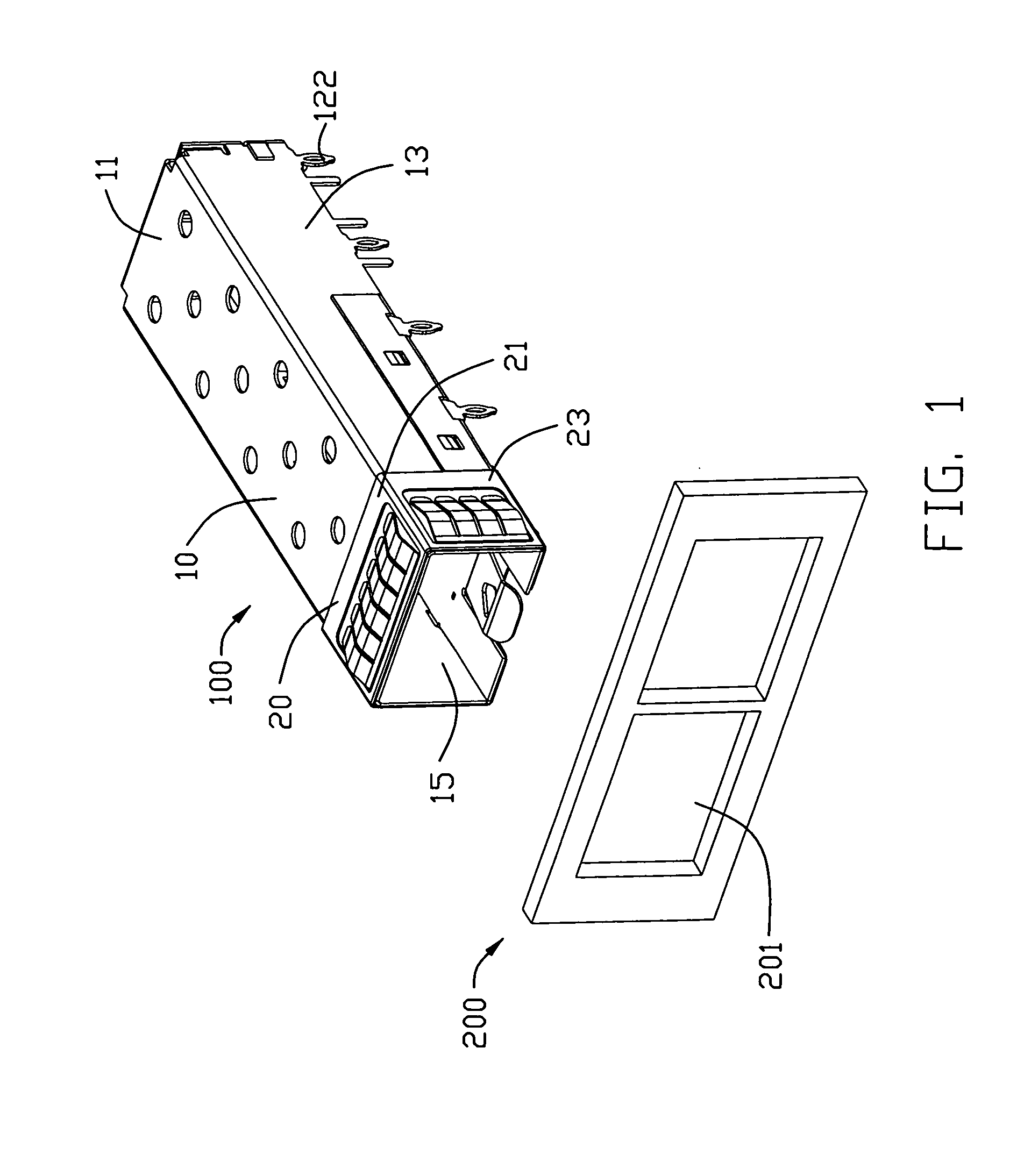
[0028]Reference will now be made to the drawing figures to describe the present invention in detail. Referring to FIGS. 1-5, a receptacle cage 100 mounted on a printed circuit board (not shown) for receiving an SFP transceiver (not shown) comprises a cage body 10 and a unitary, rectangular-shaped collar 20 mounted to a front portion of the cage body 10.

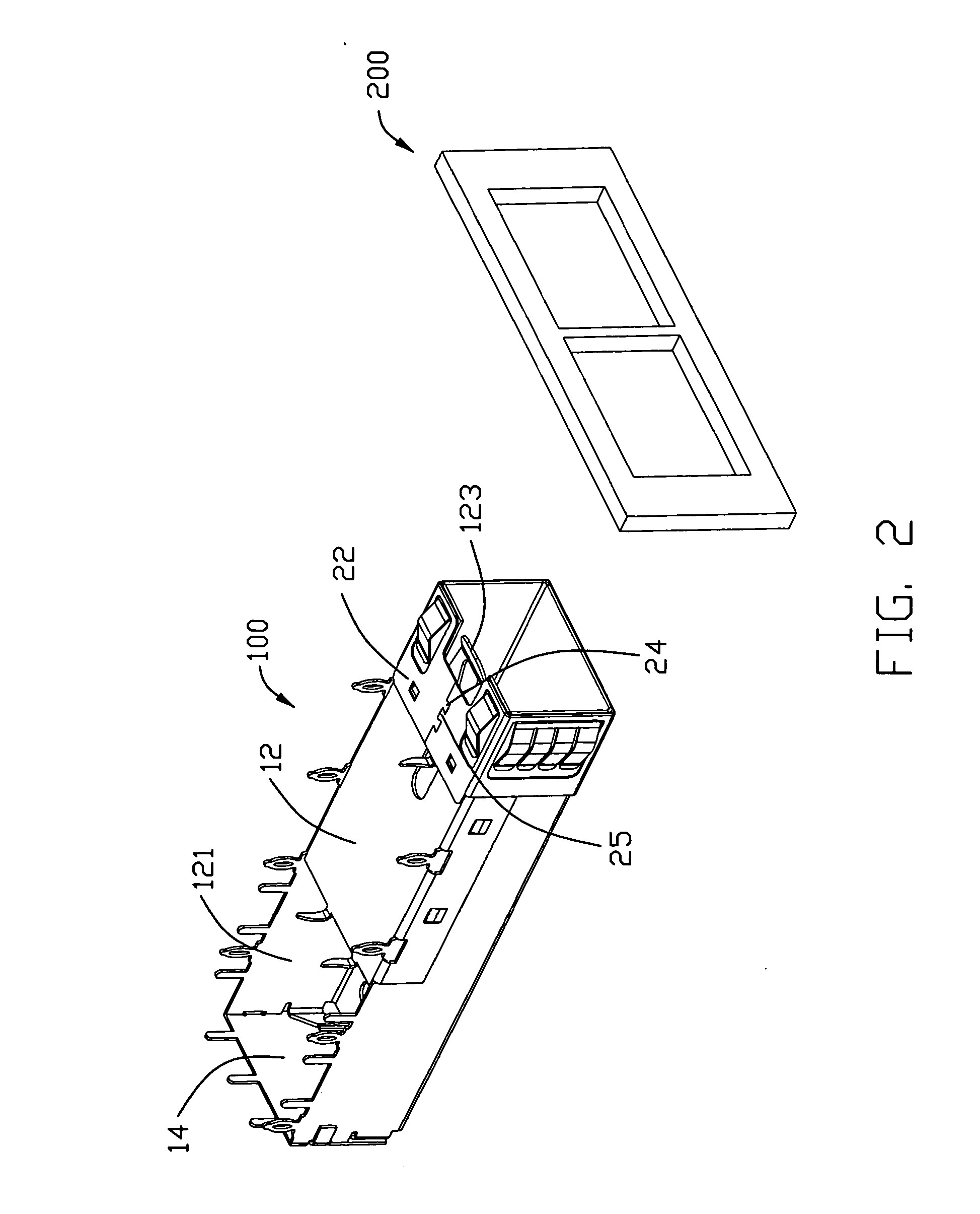
[0029]The cage body 10 has a top wall 11, a bottom wall 12 in parallel with the top wall 11, a pair of side walls 13, a rear wall 14 and a receiving opening 15 defined therebetween for receiving the SFP transceiver. The bottom wall 12 has a plurality of pins 122 extending downwardly therefrom for connecting with the printed circuit board, a recess 121 defined thereon and in communication with the receiving opening 15 and a spring plate 123 extending upwardly from the bottom wall 12.

[0030]The unitary, rectangular-shaped collar 20 is stamped from a sheet metal and attached onto the front portion of the cage body 10. The unitary, rectang...


PUM

PropertyMeasurementUnit
Electrical conductoraaaaaaaaaa

Abstract

A receptacle cage (100) for receiving a small form-factor pluggable (SFP) transceiver therein includes a cage body (10) inserted into a passage (201) defined in a chassis (200), and a conductive plate (21) attached to outside of the cage body (10), said conductive plate (21) forming a plurality of resilient fingers (26) for grounding said cage body (10) to said chassis (200). The conductive plate (21) forming a front edge portion (282) closed to the cage body (10), a connection portion (284) extending slantways and rearwardly from the front edge portion (284), and the plurality of resilient fingers (26) being listed side by side in a first direction and extending from the connection portion (284), wherein said connection portion (284) extends continuously in a direction perpendicular to the first direction and parallel to corresponding wall of the cage body (10).

Description

CROSS REFERENCE TO RELATED APPLICATION[0001]This application is a continuation-in-part of Ser. No. 12 / 286,599 filed on Sep. 30, 2008 entitled “Receptacle cage” assigned to the common assignee of the current patent application.BACKGROUND OF THE INVENTION[0002]1. Field of the Invention[0003]The present invention relates to a receptacle cage, and more particularly to a receptacle cage with a detachable front collar facilitating robust EMI shielding when the cage is mounted onto a printed circuit board with the front boot extending out of a window of a panel.[0004]2. Description of the Prior Art[0005]Historically, electrical and opto-electric modules have been connected to printed circuit boards with solder pins. Conventional approaches for soldering the pins to the circuit board include reflow soldering and hand soldering. Although solder reflow is an effective technique for electrically connecting a module to a circuit board, the heat required to achieve reflow tends to be detrimental...

Claims


Application Information

Patent Timeline
IPC IPC(8): H05K9/00H05K13/00
CPCH01R13/65802Y10T29/49002Y10S439/939H01R13/74H01R13/6582H01R13/658
Inventor GILLESPIE, BRIAN J.HSU, CHUN-HSIUNGZHANG, XIN-JIE
Owner HON HAI PRECISION IND CO LTD
Why Eureka
Try Eureka