Composite form for stabilizing earthen embankments

Inactive Publication Date: 2006-09-14
M D S K ENTERPRISES
View PDF12 Cites 21 Cited by
  • Summary
  • Abstract
  • Description
  • Claims
  • Application Information

AI Technical Summary

Benefits of technology

[0012] Using a pair of anchor rods in the foregoing manner enables a geogrid to be anchored quickly efficiently without imposing undesirable stresses on the geogrid when the geogrid is tensioned. Another point to note is that the strength of the anchoring connection (viz. the “pull-out” factor) will proportionately increase as

Problems solved by technology

In many cases, the support forms are wire cage structures which have a simple geometry but which are not necessarily well adapted for ease of manufacture or ease of use.
Further they are not necessarily well adapted to enable one support form to be coupled above and below with other like support forms, and they are not necessarily well adapted to enable a soft

Method used


Image

  • Composite form for stabilizing earthen embankments
  • Composite form for stabilizing earthen embankments
  • Composite form for stabilizing earthen embankments

Examples


Embodiment Construction

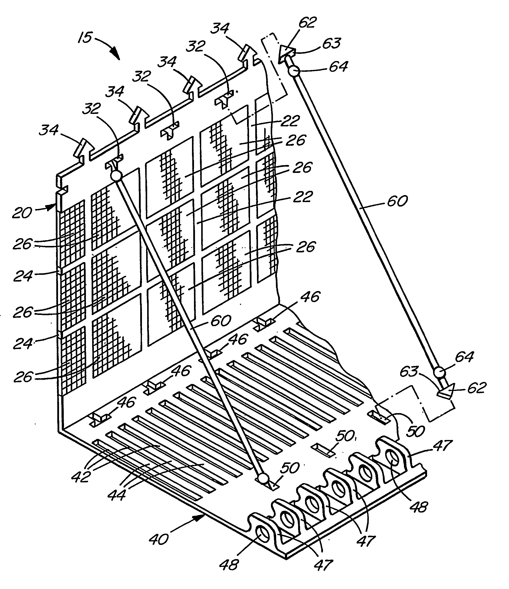
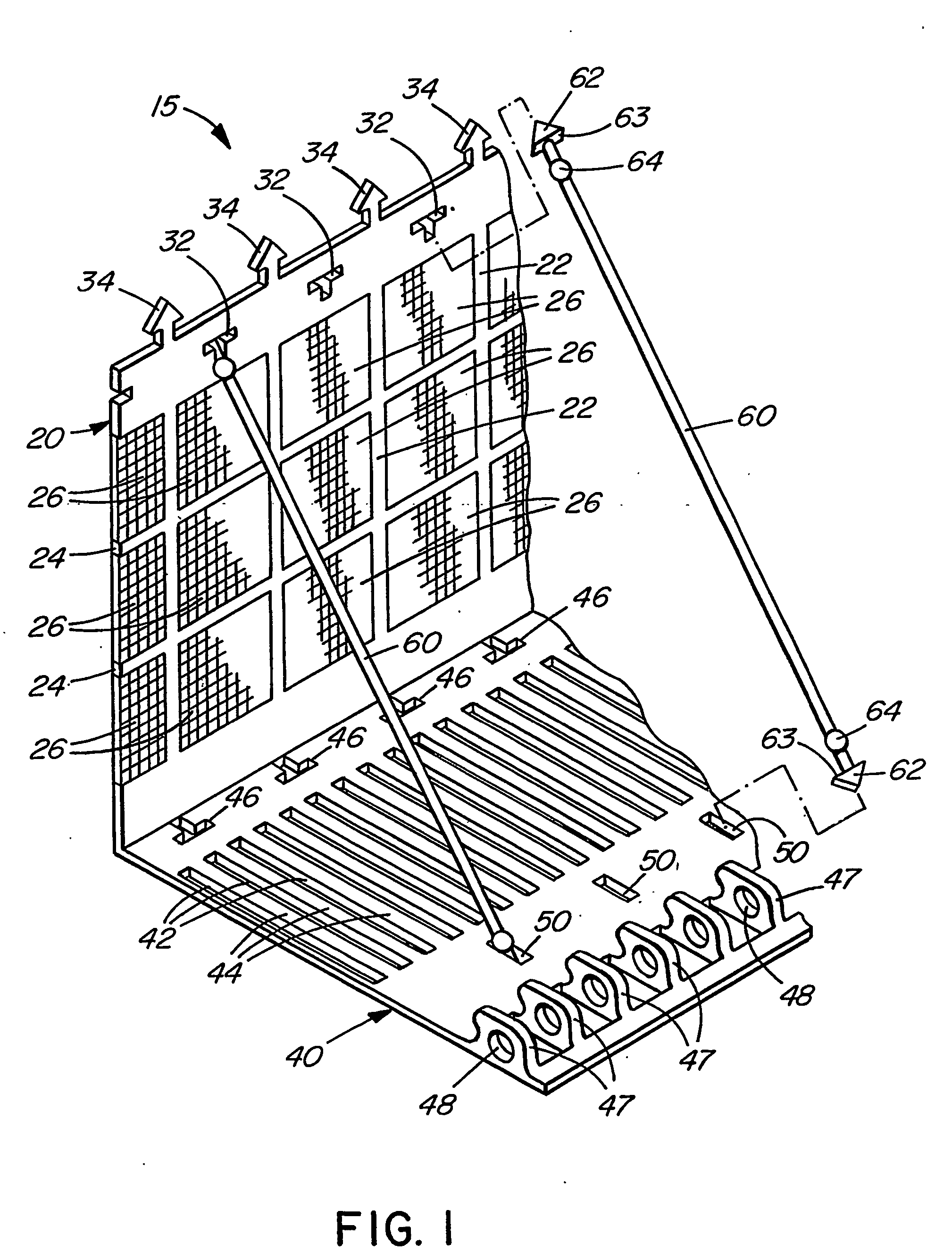
[0024] Referring now to FIGS. 1-6, there is shown a composite form generally designated 15 for stabilizing an earthen embankment (not shown). Form 15 comprises a vertically extending rectangular face section generally designated 20 integrally formed with a horizontally extending floor section generally designated 40 extending horizontally rearwardly therefrom.

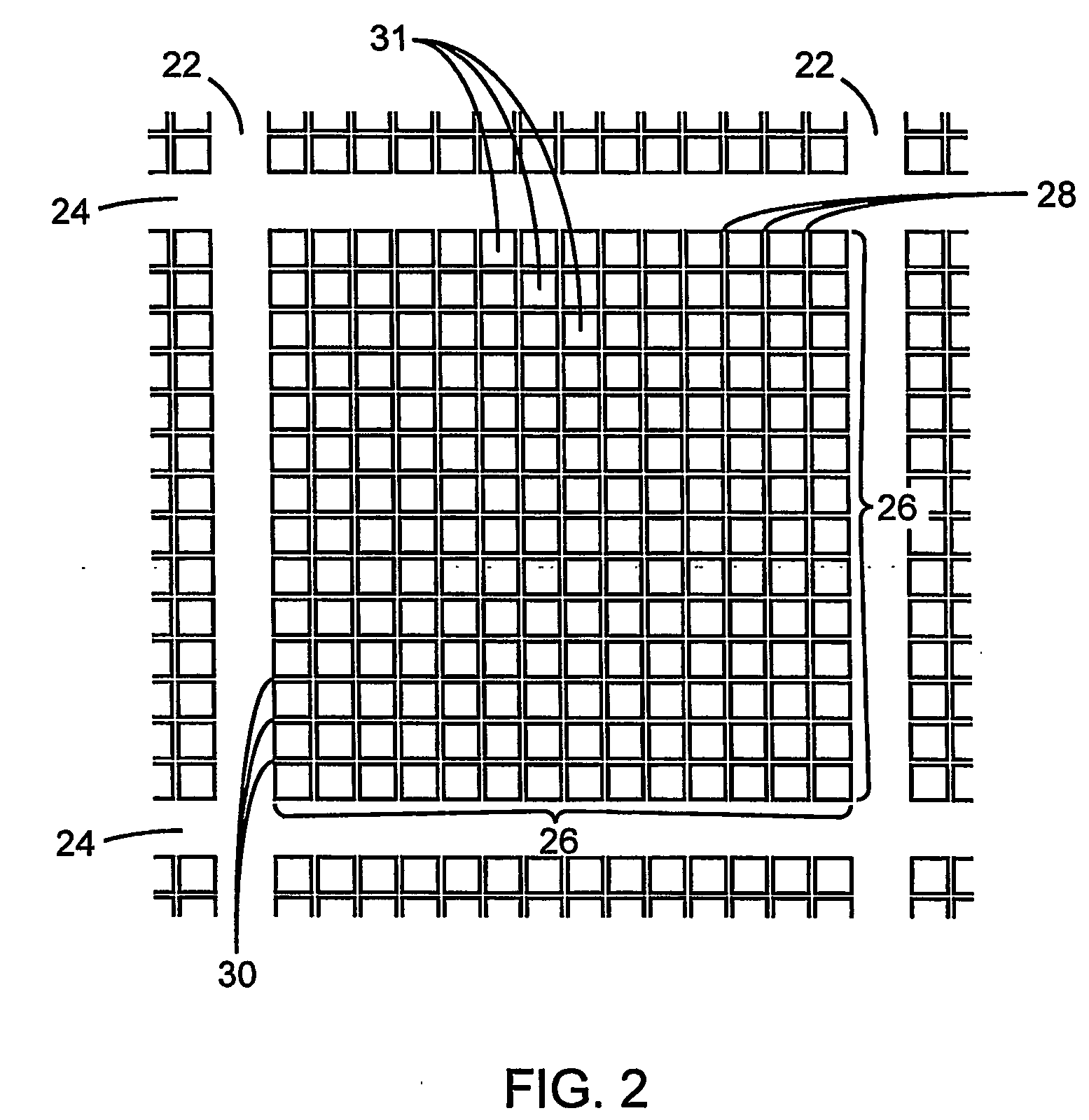
[0025] Face section 20 includes a grid formed by a plurality of vertically extending supporting ribs 22 and a plurality of horizontally extending supporting ribs 24 which intersect ribs 22. A fine mesh screen 26 (herein referred to as a hydroseeding screen) is integrally formed within each intervening region between ribs 22, 24. As best seen in FIG. 2, each hydroseeding screen 26 comprises a plurality of vertically extending ribs 28 and a plurality of horizontally extending ribs 30 which intersect ribs 28 in a manner which defines a plurality of square apertures 31 extending through face section 20.

[0026] The purpose of ribs ...


PUM


Abstract

A composite form for stabilizing an earthen embankment includes a floor section and a face section and is couplable to other like forms. The floor section includes integrally formed anchoring members for securing a geogrid with at least one anchoring rod. Advantageously, the face section of the form may included integrally formed hydroseeding screens. Also disclosed is a structure for stabilizing an earthen embankment, the structure comprising such a support form together with a geogrid anchored to the floor section of the form advantageously by a pair anchoring rods, an end portion of the geogrid being wrapped back and forth around the anchoring rods.

Description

CROSS-REFERENCE TO RELATED APPLICATIONS [0001] This application is related to U.S. provisional application No. 60 / 490,282 filed Jul. 28, 2003, entitled “COMPOSITE FORM FOR STABILIZING EARTHEN EMBANKMENTS”, naming Michael Charles Kallen as the inventor. The contents of the provisional application are incorporated herein by reference in their entirety, and the benefit of the filing date of the provisional application is hereby claimed for all purposes that are legally served by such claim for the benefit of the filing date.FIELD OF THE INVENTION [0002] The present invention relates to support forms and structures for stabilizing earthen embankments. BACKGROUND OF THE INVENTION [0003] It is well known in the prior art to stabilize an earthen embankment with support forms and associated geogrids extending rearwardly from the support forms into the embankment. In many cases, the support forms are wire cage structures which have a simple geometry but which are not necessarily well adapted...

Claims


Application Information

Patent Timeline
IPC IPC(8): E02D5/00E02D29/02
CPCE02D29/0225E02D29/0241E02D29/025
Inventor KALLEN, MICHAEL CHARLES
Owner M D S K ENTERPRISES
Why Eureka
Try Eureka