Bifurcation delivery system

Inactive Publication Date: 2006-09-14
BOSTON SCI SCIMED INC
View PDF17 Cites 39 Cited by
  • Summary
  • Abstract
  • Description
  • Claims
  • Application Information

AI Technical Summary

Benefits of technology

[0013] In some embodiments, the catheter assembly employs one or more control seals for regulating rotation of the distal end region. In at least one embodiment the control seal(s) is at least partially constructed of one or more ionic polymers or electro-active polymer (EAP) materials.
[0014] EAP materials actuate via the reversible counter-ion insertion and expulsion that occurs during redox cycling. Significant volume changes up to 30% occur

Problems solved by technology

However, problems are still encountered in orienting a stent relative to the side branch at the bifurcation of the primary and secondary passages.
Moreover, such bifurcated assemblies are typically specially manufactured at an increased cost over a more standard stent intended for single vessel deployment.
Unfortun

Method used


Image

  • Bifurcation delivery system
  • Bifurcation delivery system
  • Bifurcation delivery system

Examples


Embodiment Construction

[0028] While this invention may be embodied in many different forms, there are described in detail herein specific embodiments of the invention. This description is an exemplification of the principles of the invention and is not intended to limit the invention to the particular embodiments illustrated.

[0029] For the purposes of this disclosure, like reference numerals in the figures shall refer to like features unless otherwise indicated.

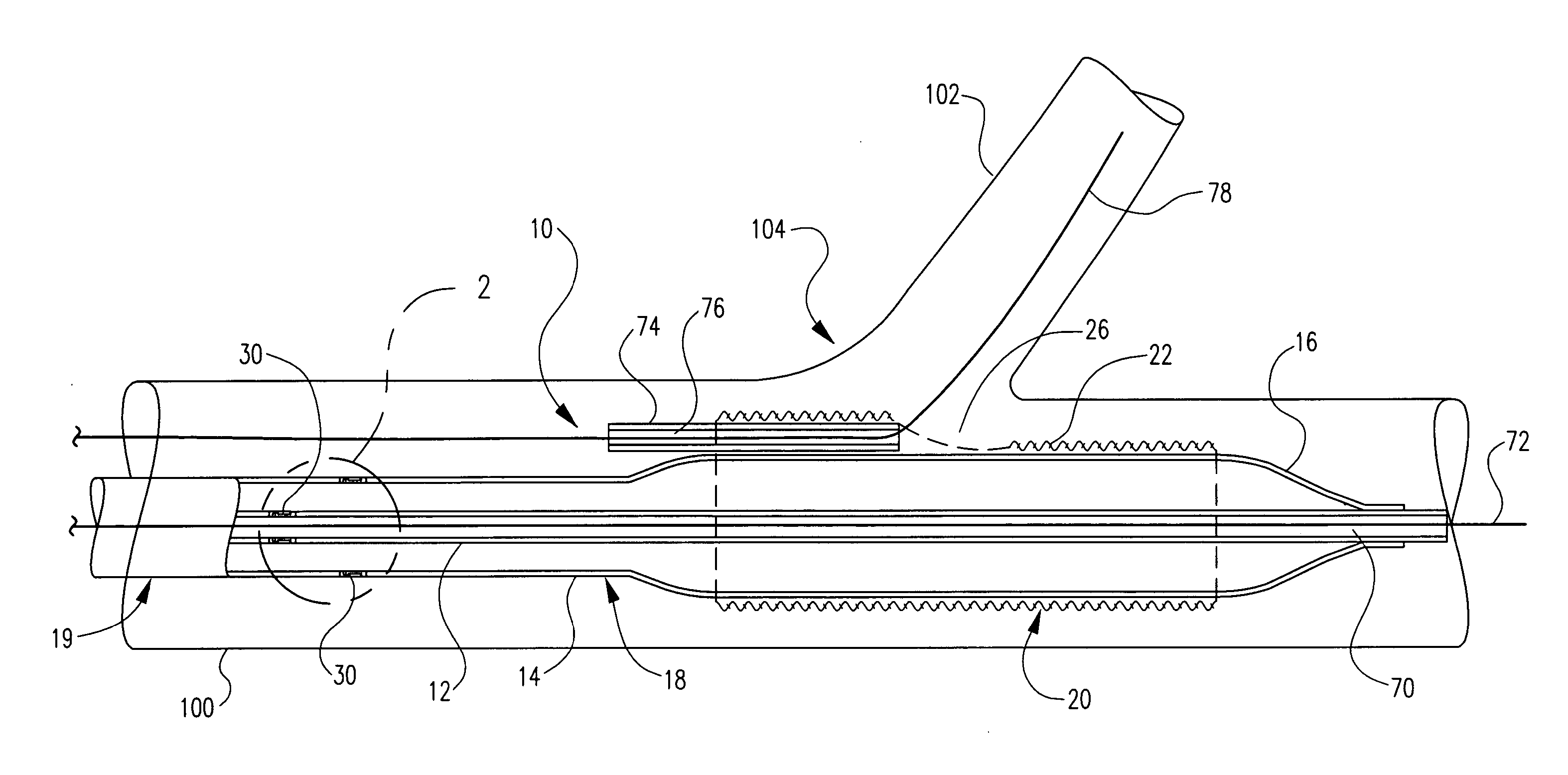
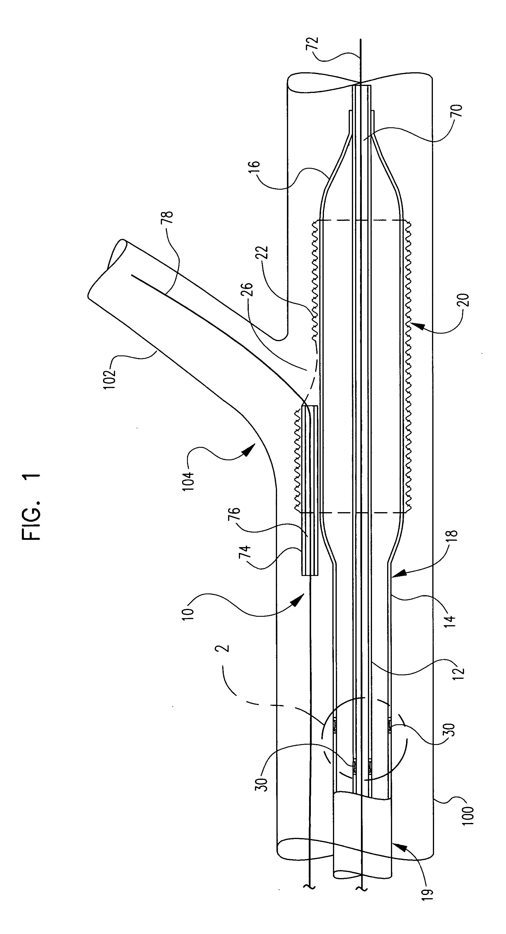
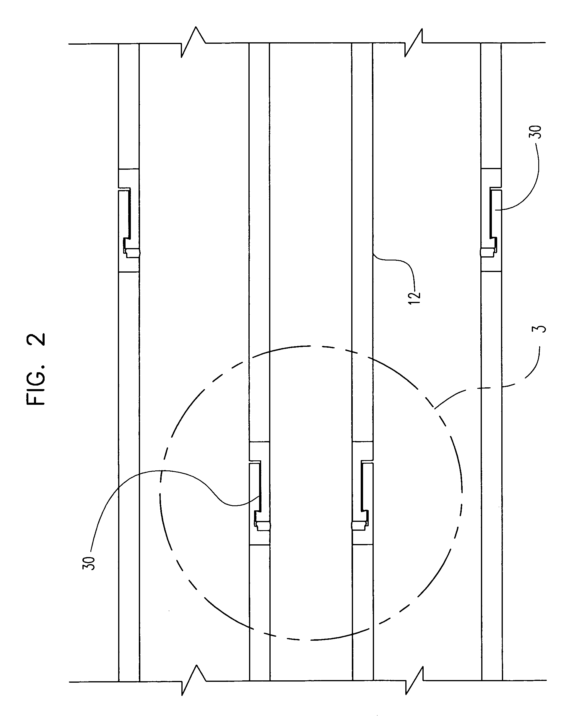
[0030] Referring now to the drawings which are for the purposes of illustrating embodiments of the invention only and not for purposes of limiting same, in at least one embodiment of the invention, an example of which is shown in FIG. 1, a catheter assembly 10 comprises an inner catheter shaft 12 and an outer catheter shaft 14. At a distal end region 18 of the assembly 10 an expandable medical balloon 16 is engaged to the shafts 12 and 14.

[0031] Balloon 16 may be a typical angioplasty, stent delivery balloon or other inflatable member which may ...


PUM


Abstract

A catheter assembly comprises a catheter shaft having a proximal region a distal region and a rotational seal therebetween. The rotational seal comprises a first component fixedly engaged to the proximal region and a second component fixedly engaged to the distal region. The components engaged in an overlapping arrangement. The rotational seal is actuatable between a non-activated and activated states. In the non-activated state the first component and the second component are separated by a gap which provides for the distal region of the catheter shaft to be rotatable relative to the proximal region. In the activated state at least a portion of the fist component and the second component being sealingly engaged together such that distal region is made static relative to the proximal region.

Description

CROSS-REFERENCE TO RELATED APPLICATIONS [0001] Not Applicable STATEMENT REGARDING FEDERALLY SPONSORED RESEARCH [0002] Not Applicable BACKGROUND OF THE INVENTION Description of the Related Art [0003] Stent delivery systems for deployment of one or more stent bodies at or around a vessel bifurcation have been proposed. Often such stents generally have an opening which allows for unimpeded blood flow into one or more side branch arteries, and / or through which an additional stent body may be deployed. However, problems are still encountered in orienting a stent relative to the side branch at the bifurcation of the primary and secondary passages. Moreover, such bifurcated assemblies are typically specially manufactured at an increased cost over a more standard stent intended for single vessel deployment. [0004] In delivering a stent to a vessel location, many current devices rely on either passive torque (e.g., pushing the stent forward and allowing the stent that is fixed on the guidewi...

Claims


Application Information

Patent Timeline
IPC IPC(8): A61F2/06
CPCA61F2/856A61F2/954A61F2/958A61F2002/30426A61F2220/0025A61M25/0043A61M2025/0058A61M2025/1045
Inventor WEBER, JANJAGGER, KARL A.EIDENSCHINK, TRACEE
Owner BOSTON SCI SCIMED INC
Why Eureka
Try Eureka