
Retractable brace

a technology of retractable braces and retractable brackets, which is applied in the direction of building parts, wall construction, building material handling, etc., can solve the problems of inability to adjust, wooden braces are very heavy, and the structure form can be very large and heavy, so as to avoid the effect of affecting the movement of workers

Inactive Publication Date: 2006-09-21
BRUNO STEPHEN M
View PDF29 Cites 35 Cited by
  • Summary
  • Abstract
  • Description
  • Claims
  • Application Information

AI Technical Summary

Benefits of technology

[0005] In one embodiment, the invention can be characterized as a method of bracing a form comprising attaching a bracket that is pivotally attached to a first end of a retractable brace to a first surface on the form, the form positioned at a first location; attaching a second end of the retractable brace to a second surface; detaching the second end of the brace from the second surface; and retracting a telescoping portion of the retractable brace while the bracket is still attached to the first surface on the form such that the retractable brace is shorter than a distance on the form from the bracket to a bottom of the form.
[0007] In a subsequent embodiment the invention includes a bracket for a retractable brace comprising an attachment member; a plurality of wings coupled to the attachment member; and at least two pin holes in each of the plurality of wings for securing the bracket to the retractable brace such that the bracket is prevented from pivoting when two pins are place through the two pin holes in each of the plurality of wings and through corresponding holes in the retractable brace.

Problems solved by technology

The structure forms can be very large and heavy and thus require sturdy braces to hold them up.
The wooden braces have weak points at cleats and turnbuckle attachments, making them undesirable.
Additionally, the wooden braces are very heavy, are not adjustable, and must be completely removed from the wooden wall forms every time the wooden wall form needs to be moved.
Further, the wooden braces tend to get in the way of workers and can not be moved without completely removing them from the wooden wall form.
Continually lifting, weather moving, installing or uninstalling the heavy and awkward wooden braces cut down on production and has been known to cause back and groin injures.
Additionally, on many job sites there is little room for storage of the large wooden braces.
The continually moving of the wooden braces is very labor intensive, tying up both men and forklifts.

Method used


Image

  • Retractable brace
  • Retractable brace
  • Retractable brace

Examples


Embodiment Construction

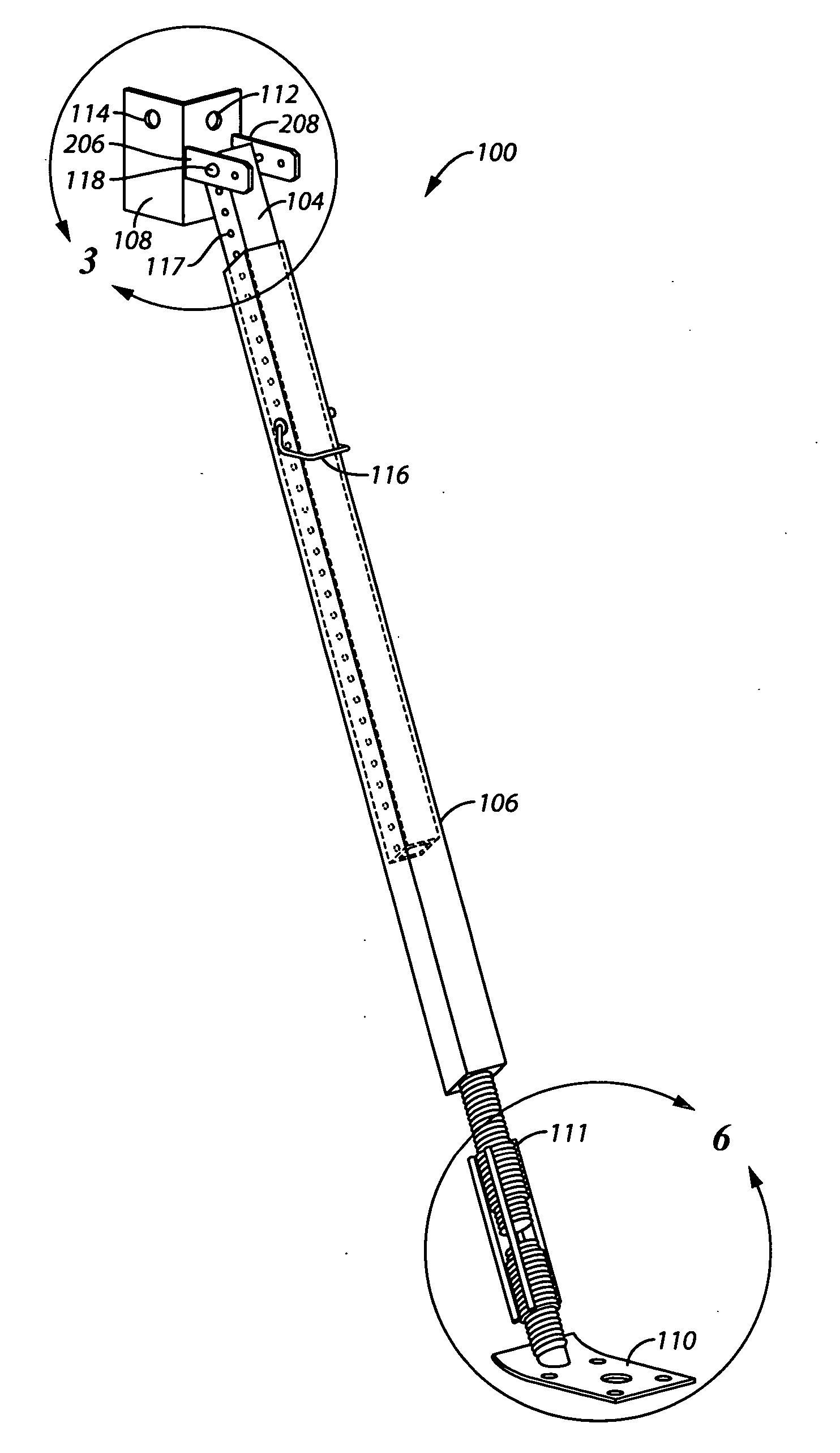
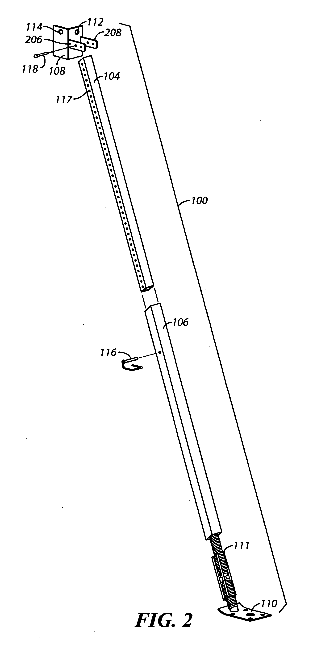
[0023] The following description is not to be taken in a limiting sense, but is made merely for the purpose of describing the general principles of the invention. The scope of the invention should be determined with reference to the claims. The present embodiments address the problems described in the background while also addressing other additional problems as will be seen from the following detailed description.

[0024] Referring to FIG. 1 a three dimensional diagram is shown illustrating a retractable brace 100 in accordance with one embodiment. FIG. 2 shows an exploded view of the retractable brace 100 of FIG. 1. As shown, the retractable brace 100 includes a telescoping portion that includes a first tube 104 and a second tube 106, a bracket 108, a foot plate 110, a swivel 111, a first bracket hole 112, a second bracket hole 114, an adjustment pin 116, and a first bracket pin 118.

[0025] The telescoping portion is pivotally coupled to the bracket 108 and is welded to the swivel ...


PUM


Abstract

One embodiment is a retractable brace comprising a telescoping support including a first tube and a second tube, wherein the first tube includes a plurality of adjustment holes; a foot plate coupled to a first end of the telescoping support; and a bracket coupled to a second end of the telescoping portion, the bracket including a plurality pin holes that align with the plurality of attachment holes in the telescoping support of the retractable brace. The bracket includes in one embodiment an attachment member; a plurality of wings coupled to the attachment member; and at least two pin holes in each of the plurality of wings for securing the bracket to the retractable brace such that the bracket is prevented from pivoting when two pins are place through the two pin holes in each of the plurality of wings and through corresponding holes in the retractable brace.

Description

BACKGROUND OF THE INVENTION [0001] 1. Field of the Invention [0002] The present invention relates to braces used in construction. More specifically, the present invention relates to retractable braces. Even more specifically, the present invention relates to retractable braces used with wall forms. [0003] 2. Discussion of the Related Art [0004] When forming large concrete walls or other concrete structures, structure forms made from, for example, wood, steel, aluminum or any combination thereof, are used to create a barrier for which concrete is poured into to form the structure. The structure forms are used when forming the concrete structure (for example, a wall, a beam or a column) and are then stripped down and moved to another location where another concrete structure will be formed. The structure forms can be very large and heavy and thus require sturdy braces to hold them up. In many instances, large wooden braces are made to hold the wooden walls in place while the concrete ...

Claims


Application Information

Patent Timeline
Patent Type & Authority Applications(United States)
IPC IPC(8): E04G21/26E04B1/00
CPCE04B2002/8688E04G17/14E04G21/26
Inventor BRUNO, STEPHEN M.
Owner BRUNO STEPHEN M
Features
  • Generate Ideas
  • Intellectual Property
  • Life Sciences
  • Materials
  • Tech Scout
  • Unparalleled Data Quality
  • Higher Quality Content
  • 60% Fewer Hallucinations
Learn More