Coalescing filter elements comprising self-sustaining, bonded fiber structures

a technology of fiber structure and coalescing filter, which is applied in the direction of gravity filter, filtration separation, separation process, etc., can solve the problems of lack of performance or too costly to be an effective solution

Inactive Publication Date: 2006-09-21
FILTRONA RICHMOND
View PDF17 Cites 43 Cited by
  • Summary
  • Abstract
  • Description
  • Claims
  • Application Information

AI Technical Summary

Benefits of technology

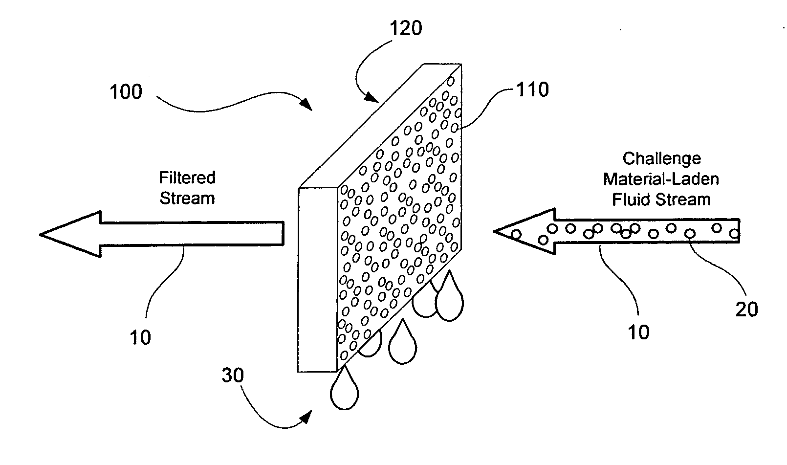
[0007] Embodiments of the present invention provide coalescing filter elements that may be used to remove oil, water and/or other liquids (“challenge materials”) from a carrier fluid stream. An illustrative aspect of the invention provides a filter element for removing a liquid challenge material dispersed in a carrier fluid. The filter element comprises a three dimensional, self-sustaining, fluid transmissive body

Problems solved by technology

While various oil coalescing filters have been produced, they have either been

Method used


Image

  • Coalescing filter elements comprising self-sustaining, bonded fiber structures
  • Coalescing filter elements comprising self-sustaining, bonded fiber structures
  • Coalescing filter elements comprising self-sustaining, bonded fiber structures

Examples


example

[0072] Exemplary filter elements according to an embodiment of the invention were produced using cellulose acetate fibers. These filter elements were produced using one or more tow ribbons comprising 1.6 dpf cellulose acetate fibers. The two ribbons were drawn between feeding rolls and drawing rolls at a ratio of 1.2-2. In the drawing section, the tow fibers were separated and crimpled so that the fibers would be bonded more uniformly later in the process. After drawing, 10% triacetin (weight % vs. weight of fiber), a plasticizer, was applied on the crimped fibers via dipping and spraying techniques. The fibers were then sent into a forming zone where they were softened and bonded to each other at points of contact to form a continuous three dimensional bonded fiber structure. This bonded structure was then cut in to specified filter element lengths.

[0073] Some of the cut filter elements were then treated with 4% w / v Repearl F-7005 (fluoroacrylate copolymer emulsion) along with 0.8...


PUM

PropertyMeasurementUnit
Surface tensionaaaaaaaaaa
Thermoplasticityaaaaaaaaaa
Porosityaaaaaaaaaa

Abstract

Filter elements are provided for removing a liquid challenge material dispersed in a carrier fluid. The filter element comprises a three dimensional, self-sustaining, fluid transmissive body comprising a plurality of thermoplastic fibers bonded to each other at spaced apart points of contact. The fibers collectively define a tortuous fluid flow path through the fluid transmissive body from a fluid inlet surface to a fluid outlet surface. At least a portion of the thermoplastic fibers comprise a surface-forming material having a surface energy that is less than a surface tension of the challenge material.

Description

[0001] This application claims priority to U.S. Provisional Application No. 60 / 663,126, filed Mar. 18, 2005, which is incorporated herein by reference in its entirety.BACKGROUND [0002] The present invention relates generally to the field of filtration devices and, more particularly, to oil and / or water coalescing filters comprising three dimensional, self-sustaining, bonded fiber structure structures. [0003] In 2004, the U.S. Environmental Protection Agency (EPA) issued a regulation effective 2007-2010 for reducing toxic particulates and pollution from heavy and medium duty diesel engines (class 4 and above, on- and off-road applications). This regulation is designed to cut diesel emissions of carbon residue (“soot”) by 90% and nitrogen oxide emissions by 95%. [0004] Crankcase blow-by gases are considered a major source of toxic particulate matter (PM) emissions. Most medium and heavy duty diesel engines operated today in North America vent combustive aerosols into the atmosphere th...

Claims


Application Information

Patent Timeline
IPC IPC(8): B01D39/14D04H1/4258D04H1/4318
CPCB01D17/10B01D39/02B01D39/163B01D17/045
Inventor WARD, BENNETT C.XIANG, JIANHARRIS, THOMAS E. JR.BINSHTOK, RONALD J.
Owner FILTRONA RICHMOND
Why Eureka
Try Eureka