Fuel injector bearing plate assembly and swirler assembly

a technology of bearing plate and assembly, which is applied in the direction of machines/engines, manufacturing tools, lighting and heating apparatus, etc., can solve the problems of difficult to adapt to the angular orientation of the nozzle, components near the front end of the combustor, and the combustor is especially susceptible to lean blowout, etc., to achieve the effect of facilitating the slidable attachmen

Active Publication Date: 2006-09-21
RAYTHEON TECH CORP
View PDF12 Cites 40 Cited by
  • Summary
  • Abstract
  • Description
  • Claims
  • Application Information

AI Technical Summary

Benefits of technology

[0010] In a more detailed embodiment, the curved surfaces are spherical.
[0011] In another more deta

Problems solved by technology

This is important because excessive air can extinguish the combustion flame, a problem known as lean blowout.
Turbine engines are especially susceptible to lean blowout when operated at or near idle and/or when decelerated abruptly from high power.
During engine operation, the components near the front end of the combustor, such as the air swirler and bulkhead, are exposed to high temperatures due to their proximity to the combustion flame.
Although conventional bearing plates are effective at accommodating translational displacement of the nozzle relative to the swirler, they cannot readily accommodate changes in the angular orientation of the nozzle.
For example,

Method used


Image

  • Fuel injector bearing plate assembly and swirler assembly
  • Fuel injector bearing plate assembly and swirler assembly
  • Fuel injector bearing plate assembly and swirler assembly

Examples


Embodiment Construction

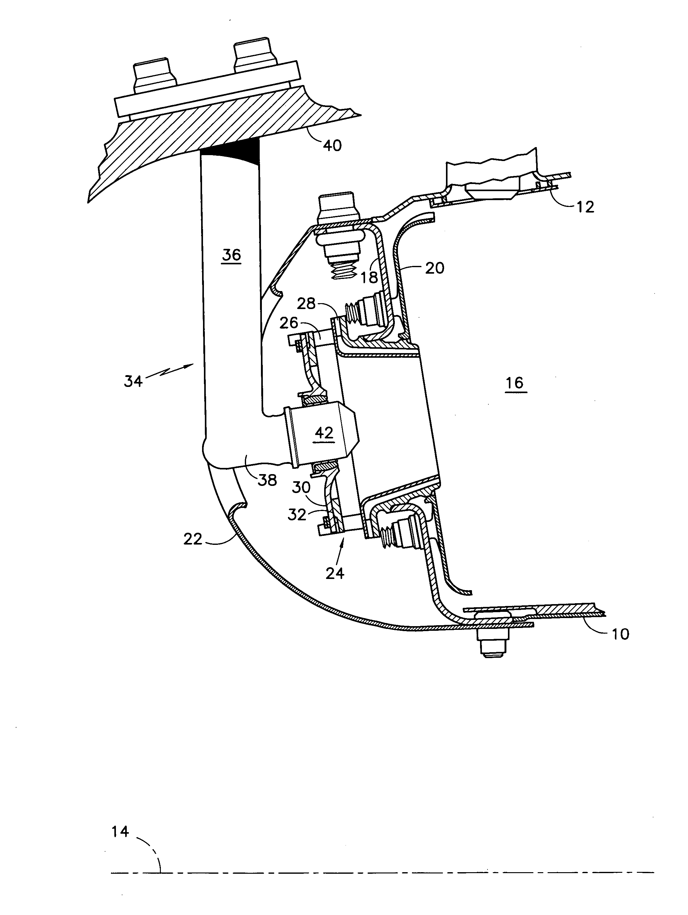
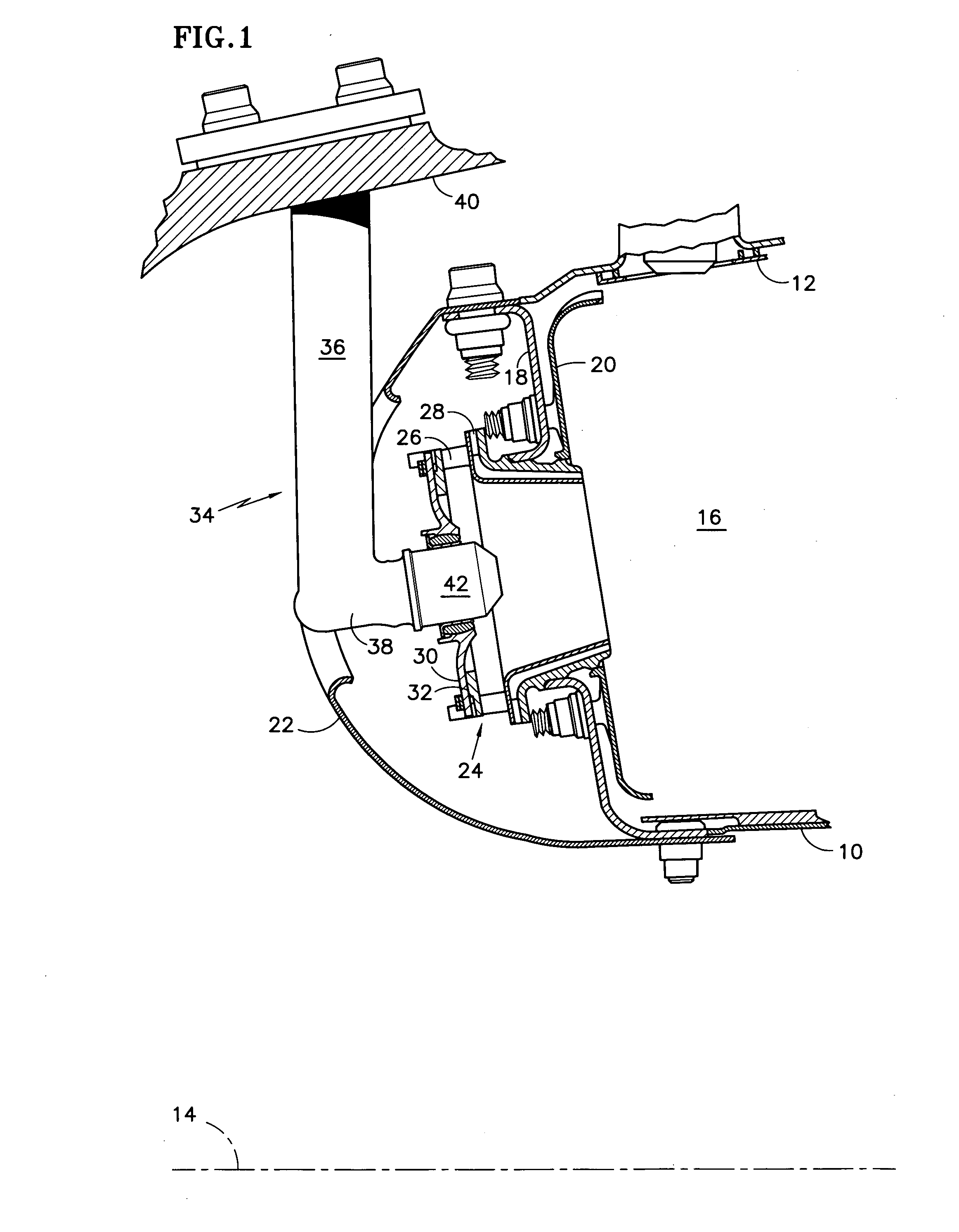
[0019]FIG. 1 shows a gas turbine engine annular combustor having inner and outer liners, 10, 12 circumscribing an engine axis 14 to define an annular combustion chamber 16. A bulkhead 18 and a bulkhead heatshield 20 extend radially between the forward ends of the liners. An annular hood or dome 22 covers the front end of the combustor. An air swirler 24 occupies central openings in the bulkhead and heatshield. During engine operation, the swirler guides air radially and then axially into the combustion chamber. Tandem sets of swirl vanes 26, 28 impart swirl to the air as it enters the swirler. A fuel injector bearing plate 30 is clamped against the forward end of the swirler tightly enough to resist air leakage past the interface or contact plane 32 between the bearing plate and the swirler but loosely enough to allow the bearing plate to slide or float radially and circumferentially relative to the swirler.

[0020] A fuel injector 34 comprises a radially extending stem 36 and a nozz...


PUM


Abstract

A bearing plate assembly for a turbine engine fuel injector includes a bearing plate 30, with an opening 80 bordered by a race 82. A swivel ball 90 nests inside the race and is rotatable relative thereto. A lock, which may be a tip bushing 108 resists disengagement of the swivel ball from the race. A fuel injector nozzle 38 extends through an opening 98 in the swivel ball. During engine operation, the ball can swivel inside the race to accommodate rotational movement of the nozzle about lateral and radial axes.

Description

STATEMENT OF GOVERNMENT INTEREST [0001] This invention was made under U.S. Government Contract N00019-02-C-3003. The Government has certain rights in the invention.TECHNICAL FIELD [0002] This invention relates to fuel injector bearing plate assemblies and air swirler assemblies for turbine engines, and particularly to assemblies that accommodate rotational movement of a fuel injector. BACKGROUND OF THE INVENTION [0003] The combustor module of a modern aircraft gas turbine engine includes an annular combustor circumscribed by a case. The combustor includes radially inner and outer liners and a bulkhead extending radially between the forward ends of the liners. A series of openings penetrates the bulkhead. An air swirler with a large central opening occupies each bulkhead opening. A fuel injector bearing plate with a relatively small, cylindrical central opening is clamped against the swirler in a way that allows the bearing plate to slide or “float” relative to the swirler. [0004] Th...

Claims


Application Information

Patent Timeline
IPC IPC(8): F23R3/14
CPCF23C5/02F23R3/14Y10T16/05F23R3/60F16L27/08F23R3/283
Inventor TANNER, KEITH M.KIRSOPP, PHILIP J.
Owner RAYTHEON TECH CORP
Why Eureka
Try Eureka