Refrigerated merchandiser

a refrigerated merchandiser and refrigerator technology, applied in the field of refrigerated cabinets, can solve the problems of excessive condensation on the colder door surface, uniform product temperature distribution may not be achieved, and significant amount of cold refrigerated air impinge, so as to reduce product temperature variation, improve distribution, and reduce product cool down time

Inactive Publication Date: 2006-09-21
CARRIER CORP
View PDF23 Cites 26 Cited by
  • Summary
  • Abstract
  • Description
  • Claims
  • Application Information

AI Technical Summary

Benefits of technology

[0015] It is an object of one aspect of the invention to provide an improved distribution of refrigerated air to the product display space of a refrigerated merchandiser to reduce product cool down time and to reduce variation in product temperature within the product display space.
[0016] It is an object of one aspect of the invention to provide an improved distribution of refrigerated air to the product display space of a refrigerated merchandiser to reduce the flow of cold refrigerated air down the front glass door of the refrigerated merchandiser.

Problems solved by technology

However, with a generally circular circulation pattern, a uniformly even product temperature distribution may not be achieved as product disposed centrally within the product display zone or on the side and rear portions of the lower shelves may not be sufficiently contacted by the circulating refrigeration air.
Additionally, as the refrigerated air passing along the top wall of the cabinet has a high horizontal velocity component, a significant amount of cold refrigerated air impinges on the inner surface of the door of the merchandiser and travels down the front of the door.
This cold air passing down the front of the door may cause excessive condensation on the colder door surfaces.

Method used


Image

  • Refrigerated merchandiser
  • Refrigerated merchandiser
  • Refrigerated merchandiser

Examples


Embodiment Construction

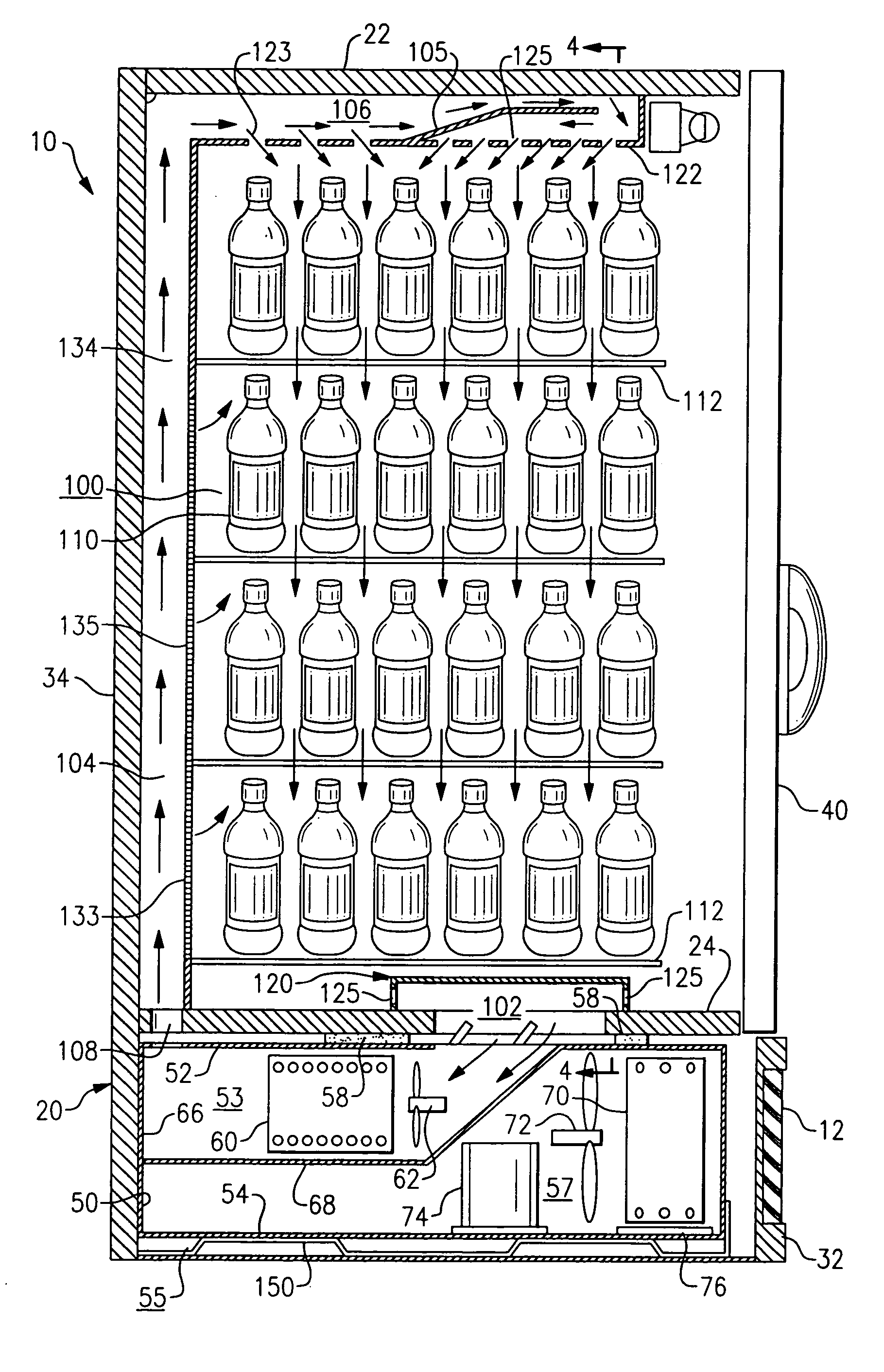
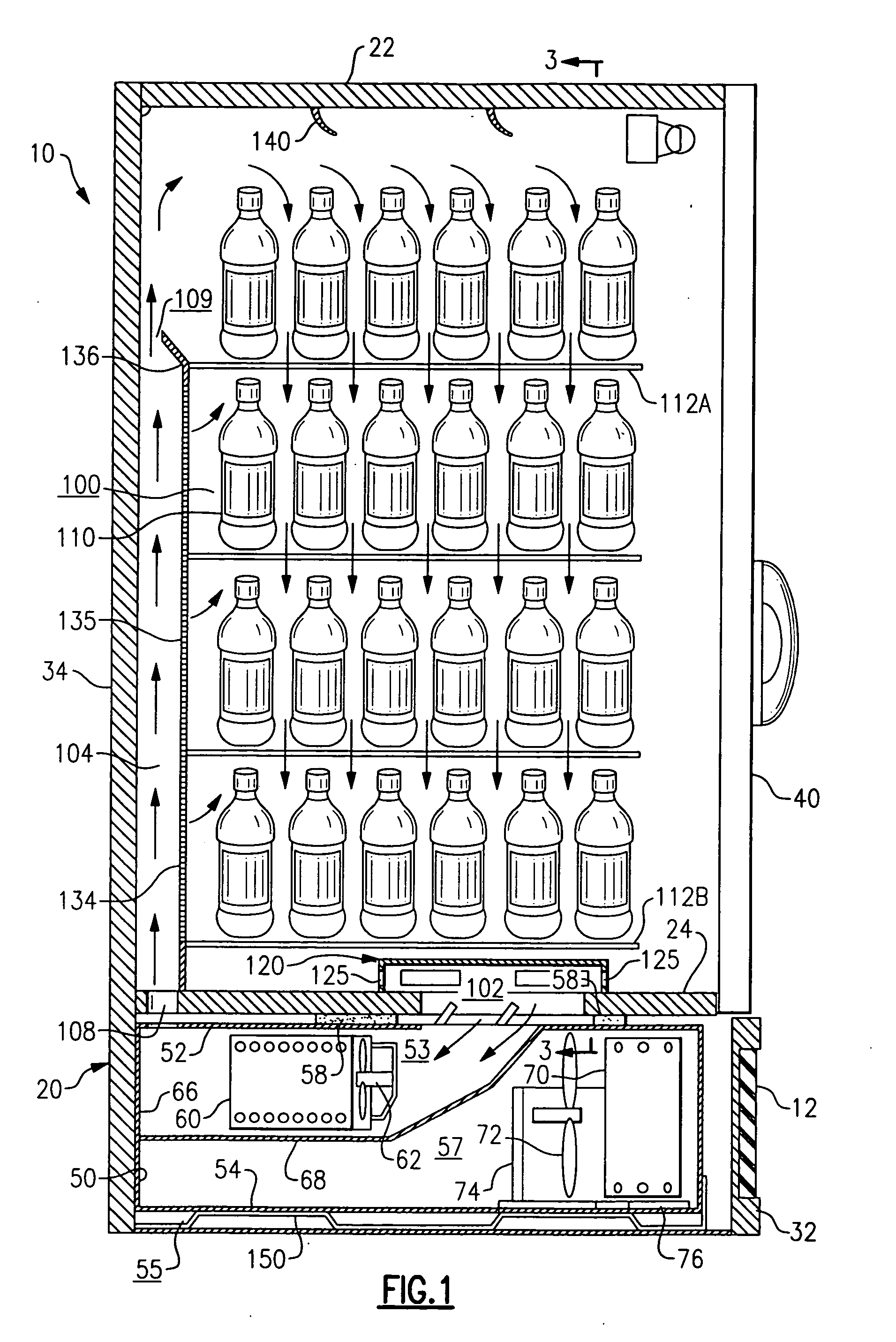
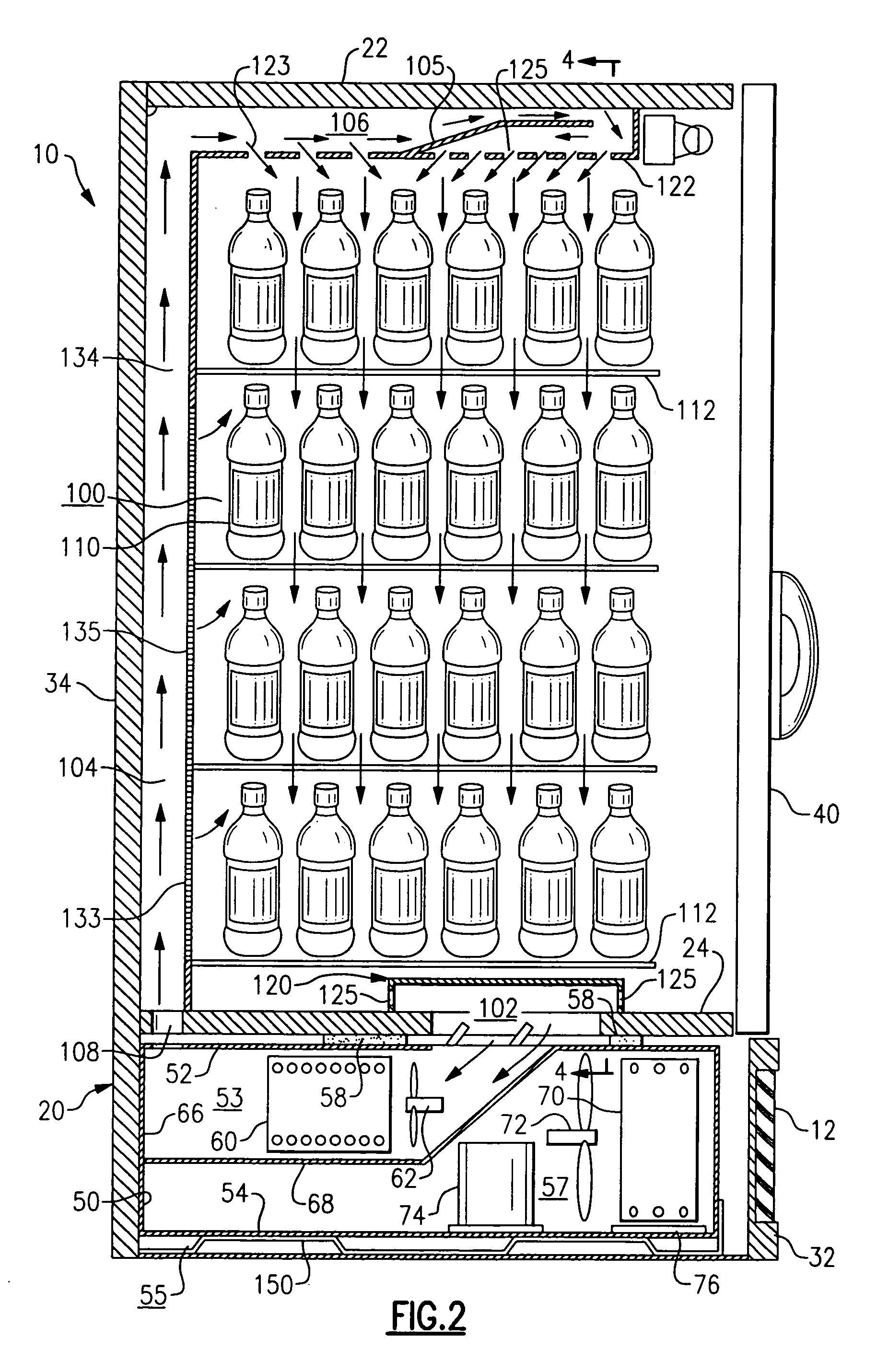
[0029] Referring now to FIGS. 1 and 2, there is depicted, in alternate embodiments, a refrigerated cold beverage merchandiser, designated generally by the reference numeral 10, including an interior product display space 100 for holding product 110 to be purchased, such as for example bottled or canned soda, milk, water, juices, fruit drinks, beer and other beverages. Although the invention will be described herein with reference to the depicted embodiments of a refrigerated cold beverage merchandiser, it is to be understood that that invention may be applied to other refrigerated display merchandisers for displaying perishable and frozen comestibles and beverages, including for example meats, poultry, fish, diary products, prepackaged frozen foods, and other products that need to be maintained in a controlled environment.

[0030] The beverage merchandiser 10 includes a cabinet 20 defining a refrigerated interior product display space 100 and a separate equipment compartment 55 dispo...


PUM


Abstract

A refrigerated merchandiser has a cabinet defining an interior product display space. A generally vertically extending air supply duct at the rear of the cabinet has an inlet for receiving the refrigerated air and an outlet at its upper end for passing the refrigerated air from the air supply duct into an upper region of the interior space along the top wall of cabinet. An evaporator fan in a compartment beneath the interior space draws air flow downwardly through the product display space and through a return air inlet in the lower wall separating the compartment from the interior space. A flow baffle may be disposed in the upper region of the interior space for directing the air downwardly into the interior space to pass through the product displayed therein and out the air return outlet in the lower wall.

Description

CROSS REFERENCE TO RELATED APPLICATION [0001] This application claims the benefit of U.S. Provisional Application Ser. No. 60 / 663,472, filed Mar. 18, 2005, and entitled COLD AIR DISTRIBUTION DUCT FOR BOTTLE COOLER, which application is incorporated herein in its entirety by reference. [0002] This application is related to the following applications subject to assignment to the common assignee of this application and filed with the United States Patent and Trademark Office on the same date as this application: [0003] U.S. patent application Ser. No. (Attorney Docket No. 210—816NP), entitled “SEALING SYSTEM FOR REFRIGERATION CASSETTE”; [0004] U.S. patent application Ser. No. (Attorney Docket No. 210—820NP), entitled “MODULAR REFRIGERATION CASSETTE”; [0005] U.S. patent application Ser. No. (Attorney Docket No. 210—879NP), entitled “MODULAR REFRIGERATION CASSETTE WITH CONDENSATE EVAPORATIVE TRAY”; [0006] U.S. patent application Ser. No. (Attorney Docket No. 210—818NP), entitled “BOTTOM ...

Claims


Application Information

Patent Timeline
Patent Type & Authority Applications(United States)
IPC IPC(8): A47F3/04F25D17/06
CPCA47F3/0408F25D17/062F25D19/00F25D2317/0651F25D2317/0665F25D2317/067F25D2317/0671F25D2331/803F25D2317/0672A47F3/00A47F3/04A47F7/28
Inventor DADDIS, EUGENE DUANE JR.MEAD, BRIAN J.
Owner CARRIER CORP
Why Eureka
Try Eureka