Superconductor cooling system and superconductor cooling method

a superconductor and cooling system technology, applied in the field of systems and methods for cooling superconductors, can solve the problems of increasing costs and physical difficulty in placement space, and achieve the effect of reducing the cooling time of the first superconductor

Active Publication Date: 2010-05-06
MITSUBISHI HEAVY IND LTD
View PDF5 Cites 21 Cited by
  • Summary
  • Abstract
  • Description
  • Claims
  • Application Information

AI Technical Summary

Benefits of technology

[0008]An object of the present invention is to provide a technique that can reduce a cooling time of a first superconductor in a case where a part of a current lead for supplying a current to the first superconductor is formed of a second superconductor.
[0011]According to the present invention, the cooling time of the first superconductor can be reduced in the case where a part of the current lead for supplying the current to the first superconductor is formed of the second superconductor.

Problems solved by technology

However, to unnecessarily increase cooling capacity of the superconducting coil cooling unit or to provide an additional superconducting coil cooling unit is not preferable, because it causes increase in costs and may be physically difficult in terms of a placement space.

Method used


Image

  • Superconductor cooling system and superconductor cooling method
  • Superconductor cooling system and superconductor cooling method
  • Superconductor cooling system and superconductor cooling method

Examples


first embodiment

1. First Embodiment

1-1. Configuration

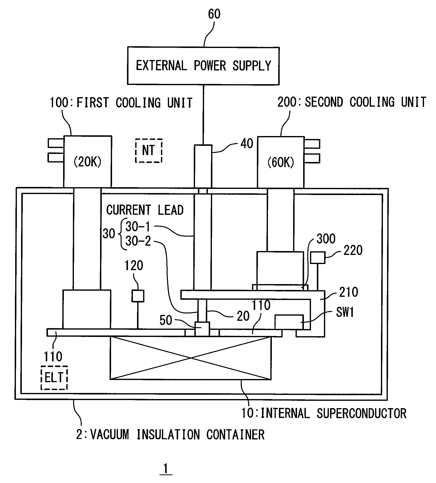
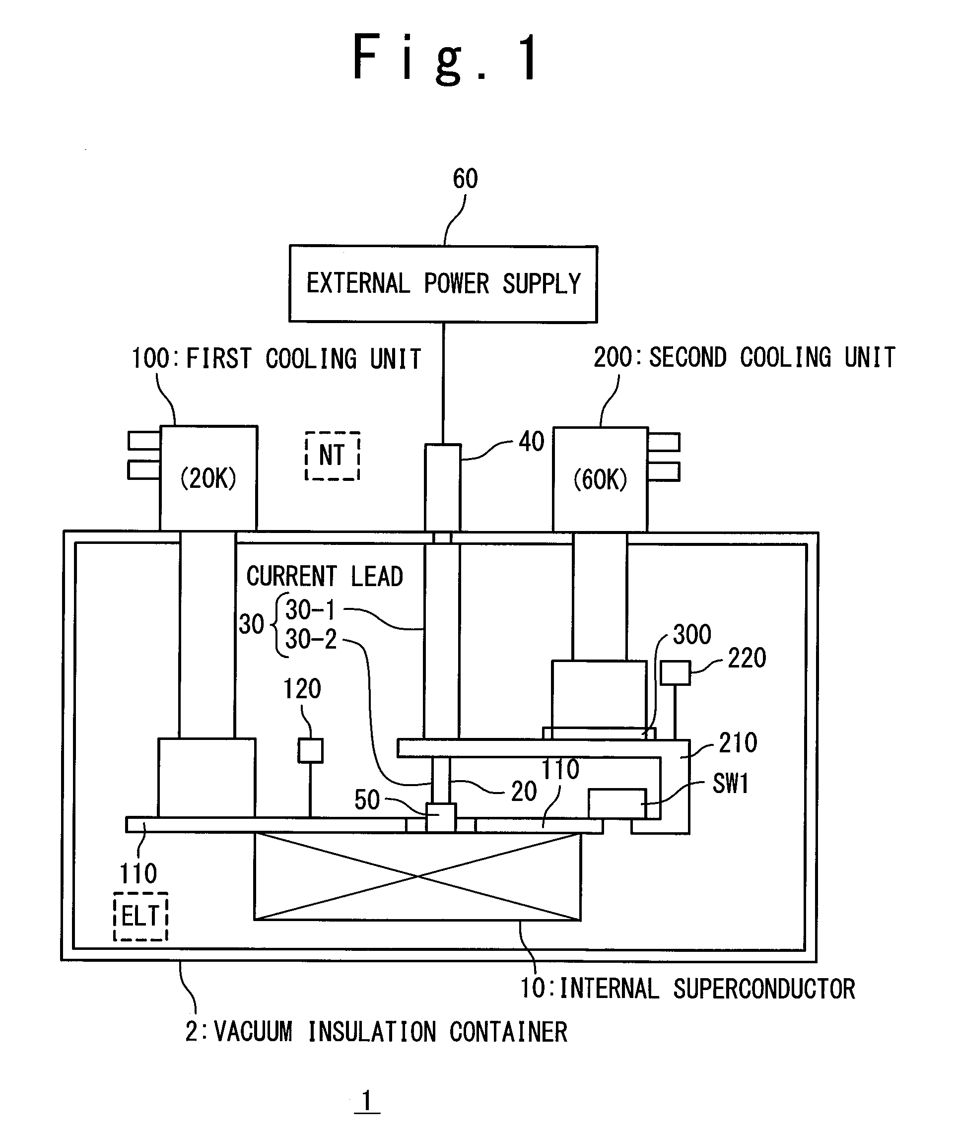
[0022]FIG. 1 is a schematic view showing a configuration of a superconductor cooling system 1 according to a first embodiment of the present invention. The superconductor cooling system 1 has a vacuum insulation container 2 in which an internal superconductor 10 is placed. The outside of the vacuum insulation container 2 is a normal temperature region (NT). On the other hand, the inside of the vacuum insulation container 2 where the internal superconductor 10 is placed is an extremely-low temperature region (ELT).

[0023]The internal superconductor 10 (first superconductor), which is used for a superconducting coil for example, goes into a superconducting state under an extremely-low temperature condition. It is possible to generate a strong magnetic field by supplying a current to the internal superconductor 10 in the superconducting state. A target temperature (first temperature) of the internal superconductor 10 at this time is 20 K for example....

second embodiment

2. Second Embodiment

2-1. Configuration

[0048]FIG. 6 is a schematic view showing a configuration of the superconductor cooling system 1 according to a second embodiment of the present invention. A description overlapping with the foregoing first embodiment will be omitted as appropriate.

[0049]According to the present embodiment, as shown in FIG. 6, a second thermal conduction switch SW2 is further provided on the second cooling conductor 210. More in detail, the second cooling conductor 210 has a cooling unit connector 210A located on a side of the second cooling unit 200, a current lead connector 210B located on a side of the superconductor 20 of the current lead 30, and the second thermal conduction switch SW2 connected between the cooling unit connector 210A and the current lead connector 210B. The second thermal conduction switch SW2 has the same configuration as the first thermal conduction switch SW1 and turns ON / OFF heat transfer between the cooling unit connector 210A and the ...


PUM


Abstract

A superconductor cooling system has: a first superconductor; a first cooling conductor used for cooling the first superconductor; a first cooling unit configured to cool the first cooling conductor to a first temperature; and a current lead configured to supply a current to the first superconductor. Here, a part of a path of the current is formed of a second superconductor. The superconductor cooling system further has: a second cooling conductor used for cooling the second superconductor; a second cooling unit configured to cool the second cooling conductor to a second temperature; and a first thermal conduction switch connected between the first cooling conductor and the second cooling conductor to ON and OFF heat transfer between the first cooling conductor and the second cooling conductor.

Description

INCORPORATION BY REFERENCE[0001]This application is based upon and claims the benefit of priority from Japanese patent application No. 2008-280366, filed on Oct. 30, 2008, the disclosure of which is incorporated herein in its entirety by reference.BACKGROUND OF THE INVENTION[0002]1. Field of the Invention[0003]The present invention relates to a system and a method for cooling superconductors.[0004]2. Description of Related Art[0005]A superconducting electromagnet device using a superconducting coil put in a vacuum insulation container is known (refer to Japanese Laid-Open Patent Application JP-H07-142237 and Japanese Laid-Open Patent Application JP-2004-111581, for example). Such a superconducting coil is cooled by a superconducting coil cooling unit and goes into a superconducting state under an extremely-low temperature condition. It is possible to generate a strong magnetic field by supplying a current to the superconducting coil in the superconducting state. Here, a member for e...

Claims


Application Information

Patent Timeline
Patent Type & Authority Applications(United States)
IPC IPC(8): H01L39/02F28F27/00
CPCF25B9/10F25D19/006H01F6/04
Inventor KAWASHIMA, HIROSHI
Owner MITSUBISHI HEAVY IND LTD
Why Eureka
Try Eureka