Electrode core drying device and method

A drying device and drying method technology, applied in the direction of drying gas arrangement, drying solid materials, non-progressive dryers, etc., can solve the problems of electrode material structure damage, large temperature difference, increased production costs, etc., to reduce drying temperature, Improve product quality and avoid secondary water absorption

Active Publication Date: 2013-07-17
GMCC ELECTRONICS TECH WUXI CO LTD
View PDF8 Cites 21 Cited by
  • Summary
  • Abstract
  • Description
  • Claims
  • Application Information

AI Technical Summary

Problems solved by technology

[0015] 2. The traditional vacuum drying process adopts batch drying, and the heat energy is mainly transferred through heat radiation in the oven. Due to the difference of the electrode core surface and the fixed heat radiation angle, the temperature difference inside the electrode core and between the electrode core and the electrode core is very large. , will cause local damage to the electrode material structure
[0016] 3. Since the electrode core materials of electrochemical energy storage devices are mostly porous materials, part of the moisture is absorbed inside the porous electrode materials, and the barrier for water molecules to escape from the electrode materials is very high, so it needs to provide high energy, while traditional vacuum drying The "static" energy provided by process vacuum heating is difficult to meet the requirements of fast drying
[0017] 4. In the transfer stage, the electrode core is exposed to the air for more than 10s. Since there is moisture in the air, and the electrode material is a loose and porous structure, it is easy to absorb moisture, so it is necessary to control the moisture content and air humidity in the environment. It must be controlled below 30% or even 20%, which greatly increases the production cost
In addition, because the transfer needs to be completed within a few seconds, the operating requirements for the operators are extremely strict. On the one hand, this will bury potential safety hazards, and on the other hand, it is not conducive to the effective control of the production process and increases the uncertainties of the system.

Method used


Image

  • Electrode core drying device and method
  • Electrode core drying device and method
  • Electrode core drying device and method

Examples


Embodiment 1

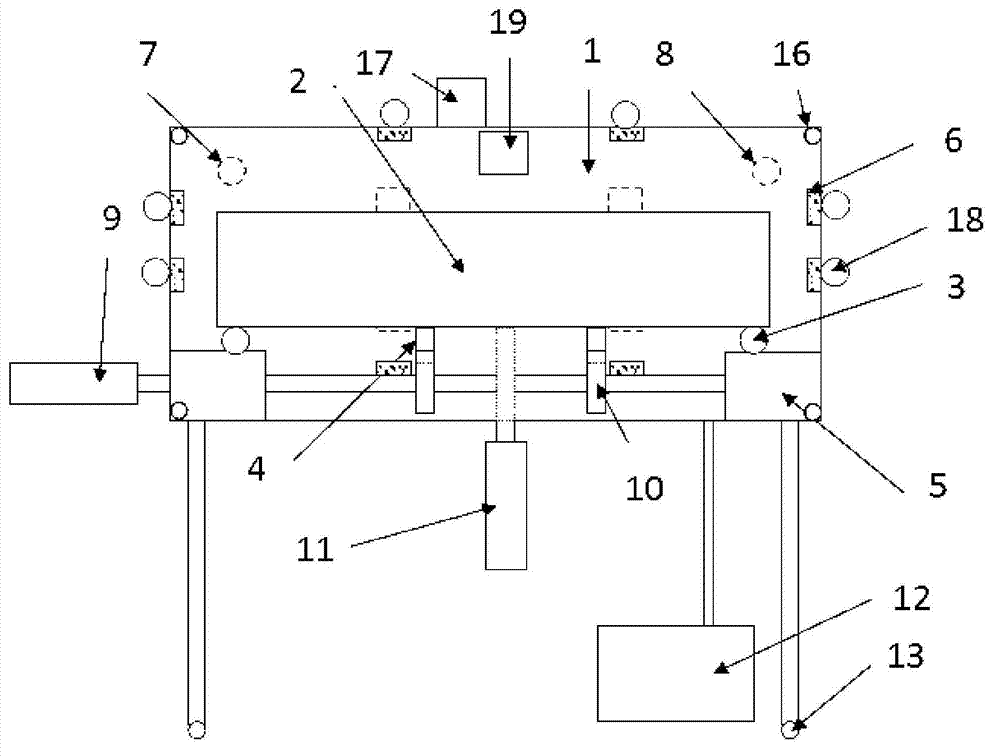
[0073] Put 60 supercapacitor electrode cores into the tray, press the button, the horizontal drive motor 9 drives the tray into the vacuum oven, and then close the oven door to start.

[0074] (1) Vacuum until the pressure inside the oven is 50Pa;

[0075] (2) Fill inert gas until the pressure in the oven reaches 0.2MPa;

[0076] (3) Extend the drive shaft of the motor in the vertical direction, insert it into the bottom groove of the tray and prop up the tray, start to rotate at a speed of 5r / min, and the built-in fan starts to rotate at the same time;

[0077] (4) The oven starts to heat, and the heating is performed by the parallel heating plates on the left, right and three panels on the rear panel. The 9 temperature probes are distributed in the 8 corners of the oven and the center of the rear panel;

[0078] (5) When the temperature in the oven reaches 150°C, the vacuum pump is automatically turned on and the fan is turned off, and the oven continues to heat at this tim...


PUM


Abstract

The invention discloses an electrode core drying device. The electrode core drying device is characterized by comprising a drying oven, a heating device, a cooling device, a tray, a tray horizontal-moving device and a tray lifting and rotating device. An electrode core drying method includes multiple times of vacuum/inert gas-filled circulating, rotary heating, forceful cooling, exposure-free air butting and the like. By the electrode core drying device and method, inert gas is filled as heat conductive medium during heating, and heating speed is high; electrode cores are rotationally heated and subjected to forced convection, temperature uniformity is improved, and more reliable data are provided for heating temperature calculation. By the aid of vacuum and gas replenishing, water overflow is better facilitated, drying temperature of the electrode cores is lowered, and product quality is improved. During cooling of the electrode cores, cooling by inert gas and forced water cooling of a heating plate are realized, cooling time is greatly shortened, drying program is automatically controlled, the drying system is movable, a flange connector is directly abutted to a liquid injection tank through the drying oven, and secondary water absorption of the electrode cores is avoided.

Description

technical field [0001] The invention belongs to the technical field of drying, in particular to an electrode core drying device and a drying method for batteries and supercapacitors. Background technique [0002] In the production process of electrochemical energy storage devices such as supercapacitors and batteries, the moisture content in the electrode material has an important impact on the performance of the product, so generally the electrode core needs to be dried before liquid injection to remove the moisture content in the electrode preparation process. Introduced moisture and moisture absorbed from the air during electrode core fabrication. For the latter, water molecules are only physically adsorbed on the surface of the electrode material, which is easier to remove, while for the former, part of the water is encapsulated in the electrode material and forms chemical adsorption with the electrode material, so higher energy is required to remove water molecules. Br...

Claims


Application Information

Patent Timeline
Patent Type & Authority Applications(China)
IPC IPC(8): F26B7/00F26B11/18F26B21/06F26B25/02
Inventor 孙伟王俊华
Owner GMCC ELECTRONICS TECH WUXI CO LTD
Why Eureka
Try Eureka