Shock resistant blood pressure measuring apparatus

Inactive Publication Date: 2006-09-21
WELCH ALLYN INC
View PDF37 Cites 0 Cited by
  • Summary
  • Abstract
  • Description
  • Claims
  • Application Information

AI Technical Summary

Benefits of technology

[0018] An advantage of the present invention is that a pressure measuring device is provided that is far more tolerable of shock and impact loads than any previously known device in the field.
[0019] Another advantage of the present invention is that the inclusion of the herein described shock absorbing and impact resistant features of the present invention does not significantly impact either the cost or the manufacture of the apparatus, nor do t

Problems solved by technology

Moreover, the mechanism is very compact as compared to typical gage movement mechanisms used for these purpose that are akin in their complexity to Swiss watches, requiring many more parts with higher tolerances, increased weight and a larger profi

Method used


Image

  • Shock resistant blood pressure measuring apparatus
  • Shock resistant blood pressure measuring apparatus
  • Shock resistant blood pressure measuring apparatus

Examples


embodiment 100

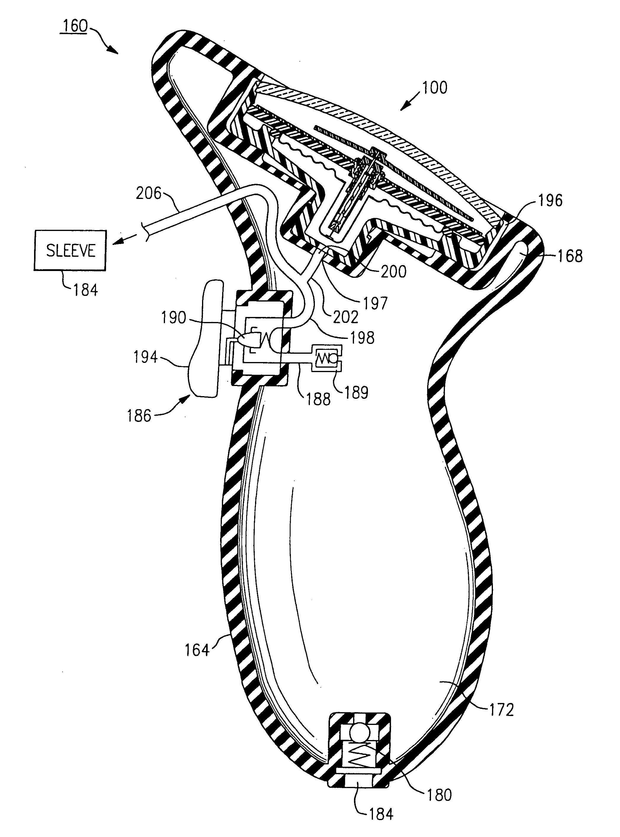
[0054] The elastomeric sleeve 160 is similar to the sleeve 60 that was previously described above and includes a retaining pocket 196 which is preferably smaller in diameter than that of a fitted gage housing 100 to provide secure engagement with the exterior thereof. The gage housing of this embodiment 100 is also identical to that previously described above and includes a contained movement mechanism, such as described by previously incorporated U.S. Pat. No. 5,966,829, which permits circumferential movement of an indicating member relative to a dial face. Hose section 202 extends to a port 200 provided in the retaining pocket 196, thereby providing a fluid path through port 148, FIG. 4, and an aligned opening 197 into the interior of the gage 100.

[0055] In operation, lower portion 172 of the sleeve 164 is squeezed, permitting air to enter the interior of the sleeve and into hose 188 through check valve 189. Initially, the bleed valve 190 is closed. Therefore, air is directed thro...

third embodiment

[0058] Alternative designs incorporating the inventive concepts described herein are possible. For example, and referring to FIG. 6, a blood pressure measuring device 220 is shown. The device 220 is defined by a cylindrical sleeve 224 having an upper portion 226 which includes a retaining pocket 228 sized to sealingly engage a gage housing 100, FIG. 4, as previously described. The cylindrical sleeve 224 is elastomeric in nature and includes lower squeezable portions 232 to enable a pneumatic function. Alternatively, a pneumatic bulb (not shown) can be provided within the cylindrical sleeve 224 to permit inflation of a connected sleeve.

fourth embodiment

[0059] Referring to FIGS. 7-9, there is herein described yet another integrated blood pressure measuring apparatus 300 that is made in accordance with the present invention. The measuring apparatus 300 according to this embodiment includes a cup 304, made preferably from a plastic molded material, that includes a defined interior cavity 308. The interior cavity 308 is sized to accommodate therein, a gage housing 310, such as described above and in previously incorporated U.S. Pat. No. 6,120,458, the bottom surface of the cup 304 including an opening 309 extending into an attached pocket housing 346. The gage housing 310 is a cylindrical member having a hollow interior that is defined by an upper retaining portion 314 and a lower engagement portion or end 318. A movement mechanism (not shown), such as described in previously incorporated U.S. Pat. No. 6,120,458 is contained within the hollow interior of the gage housing 310, the lower engagement end 318 having an opening 315, FIG. 17...


PUM


Abstract

A pressure measuring apparatus includes a gage that is at least partially imbedded within a flexible elastomeric member disposed within an interior cavity of a device housing. A shock resistant member into which the gage is inserted permits fluid interconnection between the interior of the gage having a contained movement mechanism that is responsive to fluid pressure changes and a fluid source, such as an inflatable blood pressure cuff and further provides shock and/or impact resistance for a contained movement mechanism. Additional impact/shock absorption is provided by exterior features of the apparatus, including a peripheral bumper having a plurality of raised spring-like protrusions, and rubberized and contoured features of the device housing.

Description

FIELD OF THE INVENTION [0001] The invention relates to the field of pressure measuring apparatus and more particularly to an improved shock and / or impact resistant blood pressure measuring apparatus. BACKGROUND OF THE INVENTION [0002] Sphygmomanometers are commonly known in the field of medical diagnostic medicine as devices that are used by a clinician, a caregiver or a patient in order to measure the arterial blood pressure (ABP) of the patient. In brief, these pressure measuring devices commonly include a flexible inflatable sleeve or cuff that is wrapped around the limb of a patient, such as the arm or leg, and are attached to inflation means, such as for example, a pneumatic bulb or pump. A gage mechanism that is attached to the apparatus detects fluid pressure changes within the sleeve interior that provide diastolic and systolic pressure readings when used in combination with a stethoscope. [0003] Recently, Applicants' have devised an improved gage mechanism that is useful fo...

Claims


Application Information

Patent Timeline
IPC IPC(8): G01L7/04
CPCA61B5/022G01L19/16
Inventor LIA, RAYMOND A.VIVENZIO, ROBERT L.DROMMS, RAYMOND P.SCHWAGER, BRUCE H.OSIECKI, SCOTT W.ENGLERT, ROBERT S.PARIS, CHAD P.SADDLEMIRE, DALE C.GRANT, THOMAS J.
Owner WELCH ALLYN INC
Why Eureka
Try Eureka