Cooling device for a condenser of a system for a thermodynamic cycle, system for a thermodynamic cycle, arrangement with an internal combustion engine and a system, vehicle, and a method for carrying out a thermodynamic cycle

Inactive Publication Date: 2015-10-01
MOTOREN & TURBINEN UNION FRIEDRICHSHAFEN GMBH
View PDF10 Cites 18 Cited by
  • Summary
  • Abstract
  • Description
  • Claims
  • Application Information

AI Technical Summary

Benefits of technology

[0025]The goal is also achieved by a motor vehicle that is characterized by an arrangement according to one of the previously described exemplary embodiments. With respect to the motor-driven vehicle, the advantages already explained in conjunction with the cooling device, the system, and the arrangement are realized. The energy converted by the system from the waste heat of the internal combustion engine can be used effectively either to support the internal combustion engine or for other purposes, such as to supply an on-board power supply system of the motor-driven vehicle with electrical energy.
[0026]In an exemplary embodiment the motor-driven vehicle is configured as a water craf

Problems solved by technology

The disadvantage of this is that the blower has a very high energy demand.
In this case, the cooling capacity available for the condenser is determined, so that the condenser is limited to operation on a certain temperature level and thus at a certain condensation pressure.
This necessarily leads to a performance yield lower than maximum possible yield at many operating points of a system for operating thermodynamic cycles.
If, furthermore, the temperature of the working medium at the outle

Method used


Image

  • Cooling device for a condenser of a system for a thermodynamic cycle, system for a thermodynamic cycle, arrangement with an internal combustion engine and a system, vehicle, and a method for carrying out a thermodynamic cycle
  • Cooling device for a condenser of a system for a thermodynamic cycle, system for a thermodynamic cycle, arrangement with an internal combustion engine and a system, vehicle, and a method for carrying out a thermodynamic cycle
  • Cooling device for a condenser of a system for a thermodynamic cycle, system for a thermodynamic cycle, arrangement with an internal combustion engine and a system, vehicle, and a method for carrying out a thermodynamic cycle

Examples


Embodiment Construction

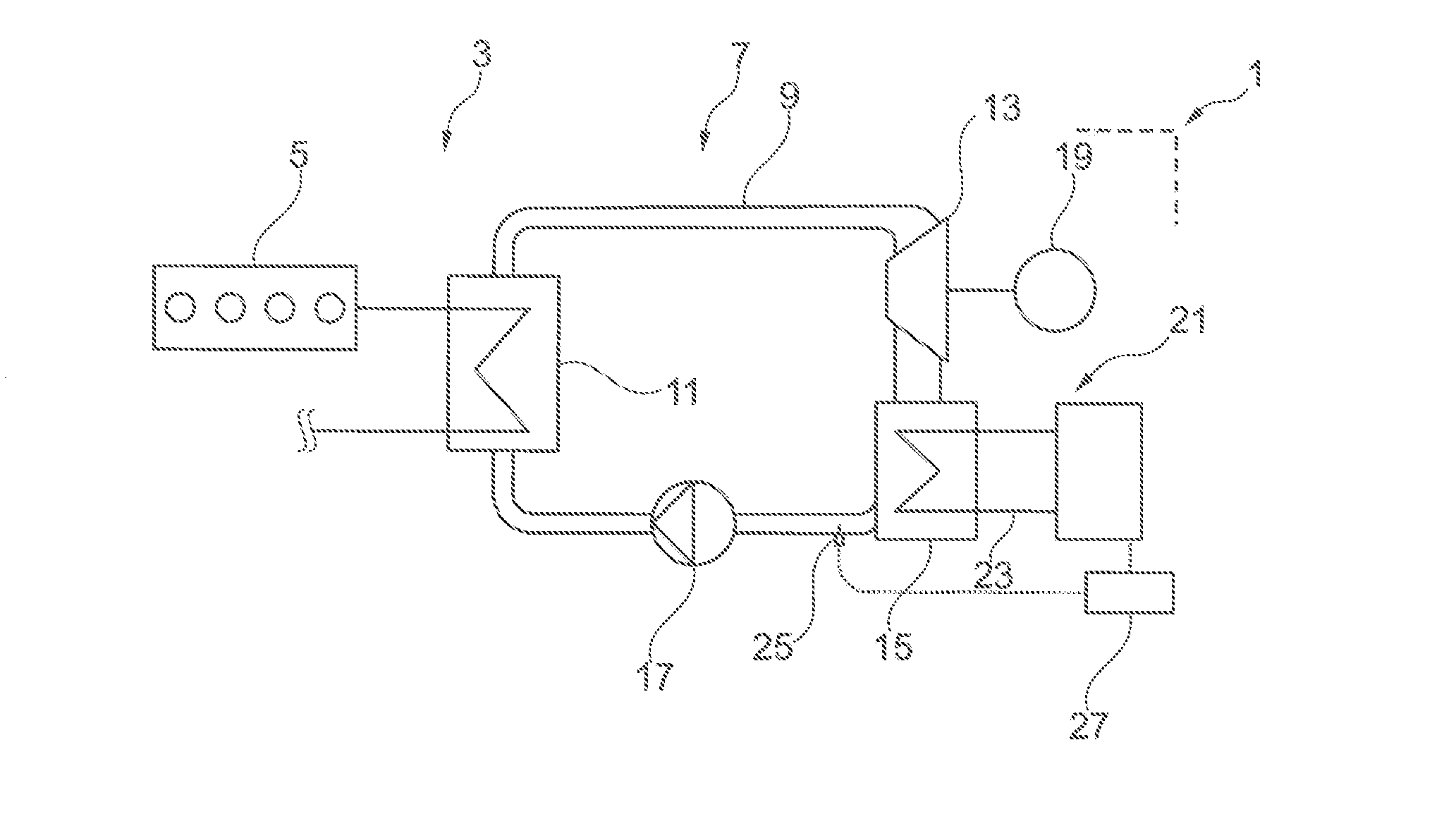
[0037]FIG. 1 shows a schematic diagram of an exemplary embodiment of a motor-driven vehicle 1, which comprises an arrangement 3 consisting of an internal combustion engine 5 and a system 7 for operating a thermodynamic cycle, here in particular an organic Rankine cycle (ORC). The motor-driven vehicle 1 is preferably configured as a ship. Alternatively, however, an embodiment of the motor-driven vehicle 1 as a rail vehicle, as a mining or construction vehicle, as a defensive vehicle, as a truck, or even as a passenger vehicle is also possible.

[0038]The use of the arrangement 3 is not limited to motor-driven vehicles; instead, it can be used in other areas as well, including stationary uses of the internal combustion engine 5 to operate pumps on an offshore drilling rig, for example, where the waste heat of the engine can be put to positive use.

[0039]Finally, the system 7 is not limited to use in an arrangement with an internal combustion engine 5. On the contrary, it can be used in o...


PUM


Abstract

A cooling device for a condenser of a system for a thermodynamic cycle, with a coolant circuit, wherein a conveying device for conveying a coolant through the coolant circuit is provided, and wherein the coolant circuit includes a cold branch downstream from a cooling point for the coolant and a hot branch upstream of the cooling point. The conveying device has a variable output, and/or the coolant circuit has a connecting line between the hot branch and the cold branch. A mixing device is provided, by way of which a variable portion of coolant can be supplied from the hot branch to the cold branch via the connecting line, bypassing the cooling point.

Description

CROSS-REFERENCE TO RELATED APPLICATIONS[0001]The present application claims priority of DE 10 2014 206 026.5, filed Mar. 31, 2014, the priority of this application is hereby claimed and this application is incorporated herein by reference.BACKGROUND OF THE INVENTION[0002]The invention pertains to a cooling device for a condenser of a system for a thermo-dynamic cycle, to a system for a thermodynamic cycle, to an arrangement consisting of an internal combustion engine and such a system, to a motor-driven vehicle with a corresponding arrangement, and to a method for carrying out a thermodynamic cycle.[0003]Thermodynamic cycles of the type in question here are known as such. A working medium is heated, in particular vaporized, in a vaporizer, and then expanded in an expansion device, wherein heat of the working medium taken up in the vaporizer is converted to mechanical energy. The working medium is then cooled, in particular condensed, in a condenser, and sent back to the vaporizer ag...

Claims


Application Information

Patent Timeline
IPC IPC(8): F25B39/04
CPCF25B39/04F01K23/065
Inventor WAIBEL, NIKLASSTECHER, DANIELNIEMEYER, JENSLORENZ, MAXHORBACH, TIMFAST, GERALDMULLER, MATHIAS
Owner MOTOREN & TURBINEN UNION FRIEDRICHSHAFEN GMBH
Why Eureka
Try Eureka